
Lost foam casting engine block

Lost-die mold structure with cylinder liner Engine block
The technology of the lost foam process for casting the engine body is mature, from single cylinder to six cylinders to V cylinders, from cylinder liners to cylinder liners, etc., and gradually realizes mass production and use, especially in the past two years. The lost mold process casts the 465 series of water-cooled upright engine blocks with cylinder liners.
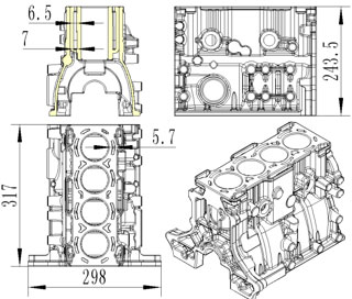
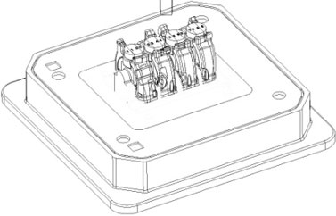
Refer to the technical requirements of the castings in Figure 1: casting material HT250, white mold material: STMMA (copolymer), the microstructure of the casting should be pearlite, the matrix content should be no less than 90%, and a small amount of ferrite and phosphorus eutectic is allowed. The graphite is uniformly distributed in a fine sheet shape. The internal stress is eliminated, the hardness of the casting is 187-255HBS, and the tensile strength is ≥250N/mm2. Product dimensions: 317X298X243.5 (unit: mm). Casting dimensional tolerance CT7 (GB/T6414-1999).
Difficulties in casting of such engine body lost foam process:
1. Casting of cooling water chamber, the gap of the cooling cavity of the machine is changed from 6.5mm to 7mm, and the sand hole of the end face is small, the local width is only 5.7mm, the cooling cavity is coated and sanded. It is difficult to clean up.
2. Zero defect in cylinder processing, inner crankshaft hole and camshaft hole machining.
3, the shape of multiple positioning screw column, all screw holes should be smooth, no defects, cracks. The body has no wall thickness of 5mm and can be tested by water pressure of 0.4Mpa. It must not leak for 2min. The lubricating oil passage shall pass the oil pressure test of 0.6MPa pressure for 1min and shall not leak.
4. Castings are not allowed to have cracks, cold partitions, shrinkage, pinholes, foreign inclusions and other casting defects that reduce strength.
In orderto solve the above problems, it is necessary to introduce a new lost foam mold structure with a cylinder liner engine body. The mold process should be consistent with the casting equipment of the foundry, in accordance with the lost foam casting production line of the foundry, and the complete set of casting manufacturers. The lost foam production process is combined, and the mold structure adopts the following technical solutions:
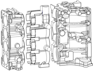
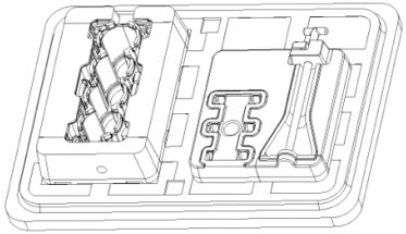
First, determine the sharding scheme, as shown in Figure 2: The structural analysis of the body, combined with the casting table, coating, bonding process, etc., the body should consider the process of using the resin sand core under the cooling water chamber during casting. This process should focus on:
First: the white mold segmentation helps the resin sand core to be placed. The white mold profile is divided into two pieces from the center of the four-sided through hole of the shape of the cooling cavity of the body. The split surface is a straight plane, which is basically located at two-thirds of the cylinder from the top to facilitate the placement of the sand core. Conducive to the bonding of white mold.
Second: When the resin sand core is coated, the paint is prevented from falling on the white mold bonding surface when the white mold is placed. From the above, the cylinder part can be integrally formed. The piece is separated from the large piece at the bottom of the cylinder. When combining, the resin sand core and the small piece are brushed together. If the small cylinder is covered with paint, the air gun can be used. Slightly blow off, and then put the small piece and the sand core together in a large piece to bond, which can effectively prevent the paint from entering the white mold bonding surface.
Third: the resin sand core prevents displacement during the tapping and casting process in the sand box, and the resin sand core can also be fastened in the sand box. When the resin sand core is designed, the through hole of the body can be extended to make a protruding process. The process boss of the surface of the through hole is 10-25mm, and the sand is positioned by the process boss to the sand core during the suction negative pressure process.
Fourth: prevent the resin sand core from being burned in the casting, causing iron-clad sand, controlling the thickness of the coating of the resin sand core and the thickness of the sand core body, and arranging a coating gap of 0.8 mm on one side between the sand core and the white mold. .
Fifth: Prevent the resin content of the resin sand core from being too much, causing the gas generation amount in the casting process to be too large, and increasing the pores of the casting. When designing, the resin boss core is over-thickened to reduce the weight of the core and the resin. The content can also be considered to replace ordinary sand with Baozhu sand (powder).
Sixth: Control the volume of the water chamber to meet the conditions of use of the body. When drafting, do the drafting of the white mold and the sand core so that it can be demoulded smoothly without affecting the volume of the water chamber.
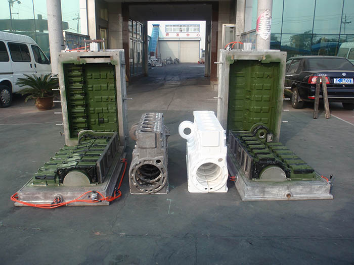
Secondly, according to the splicing scheme, it is necessary to divide 3 sets of molds, 2 sets of lost mold dies and 1 set of hot core box dies, and here mainly explain the structure of the lost mold. According to the automatic vertical molding machine of the foundry manufacturer, the first set of mold structure adopts automatic machine mold, automatic filling, automatic heating and cooling, automatic core pulling, automatic ejection, white mold can realize automatic production, reduce labor intensity and save casting. Cost, increase production efficiency.
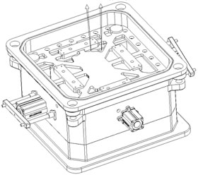
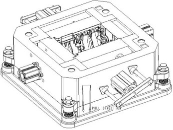
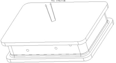
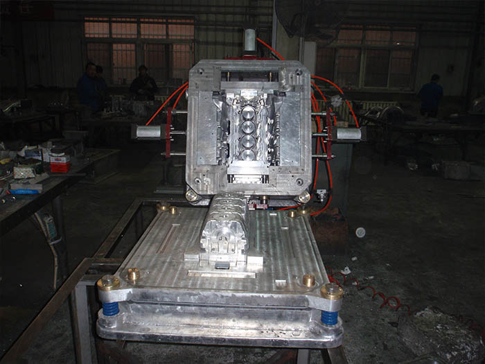
As shown in Fig. 3, the mold is divided into upper and lower molds, and the mold structure of the upper, middle and lower air chambers is adopted as a whole, and the parting surface of the mold is between the middle and lower air chambers, and the parting surface has upper, The positioning mechanism and sealing system of the lower die. As shown in Figure 4: the shape of the upper molding body, the upper mold consists of the upper air chamber, the middle air chamber, four movable inserts, the core pulling mechanism, the spring mechanism, the charging mechanism, the sealing system, and the spray cooling system. composition. As shown in Fig. 5: the inner cavity of the lower molding body, the lower mold has a lower mold air chamber, a core, a movable insert, an ejection mechanism, a sealing system, and a spray cooling system.
The upper, middle and lower air chambers and the large side core inserts are made of cast aluminum alloy, the small and thin wall inserts are made of forged aluminum alloy, and the guiding system and positioning system are made of stainless steel and brass.
The four corners of the upper air chamber and the middle air chamber are connected by spring bolts. When the mold is not tight, a 12 mm gap is reserved under the spring force, which has three functions. First, the product has a wall thickness of 5 mm, can be vented during charging, and can be pre-opened. Second, the mold helps to discharge the cooling water. Third, the upper and lower molds can achieve delayed contact and improve the service life of the mold. A sealing system is arranged between the upper air chamber and the middle air chamber connecting surface to prevent leakage of hot steam and cooling water when the mold is closed.
The four movable inserts and the core-pulling mechanism of the inner chamber of the upper mold complete the automatic forming of the four-sided shape of the 465 body. The core pulling mechanism is composed of a cylinder, a guide column, a guide sleeve and a sealing system. The cylinder is fixed on the outdoor side of the medium gas with stainless steel screws. The guiding mechanism is designed according to the size of the movable insert. The large double-column guide bushing of the movable insert guides the movable insert (front and back of Fig. 4) through the guide post. Connected to the cylinder. The small movable insert directly connects the cylinder head and the movable insert, and the directing of the cylinder straightens out to guide the movable insert (left and right of Fig. 4). The working principle of automatic forming is to flush compressed air into the cylinder of the cylinder to drive the piston movement of the cylinder. The piston is connected with the movable insert through the thread or the guide rod. The piston moves the movable insert to complete the opening and closing action by moving forward and backward. The five advantages of the automatic core-pulling mechanism: high efficiency, high precision, good surface quality, good stability and light labor intensity.
Filling mechanism design: In order to make the white mold full and smooth, the surface of the medium air chamber is inserted into the automatic gun through the core insert, and the main and auxiliary guns are combined, two on each side, a total of 8 Fill the gun.
Heating and cooling design: Install the spray copper tube in the upper and lower mold air chambers, connect the cooling water, and realize automatic spray cooling.
Sealing system design: including four parts, the sealing system of the upper and lower air chambers and the forming machine template, the sealing system of the core cylinder and the guide sleeve and the middle air chamber, the sealing system of the parting surface, the sealing of the joint surface of the material gun and the middle air chamber The sealing system between the system and the upper air chamber mentioned above, the sealing element is generally made of a silicone sealing strip or a sealing ring.
The core of the lower mold is fixed on the lower mold air chamber by stainless steel screws, the movable insert is positioned and guided on the core, the automatic mold release mechanism is located in the lower mold air chamber and the parting surface, and the automatic mold release mechanism is removed from the mold. The ejector cylinder, the top column, the guide post and the guide sleeve are composed of five parts, and the stripping plate thickness is 20 mm. The mounting groove of the stripping plate is located on the parting surface of the lower air chamber, and the four corners of the slot respectively have the cylinder and the stripping plate. The connecting hole is provided with a copper guiding sleeve, and the cylinder and the stripping plate are connected through the guiding column. The ejector cylinder is fixed in the lower mold air chamber, and four column-mounted cylinders are respectively arranged around each connecting hole in the lower mold gas chamber. In the insert mounting groove, the remaining part of the 12MM edge is hollowed out, and the live block and the product edge are on the stripper. The working principle is that the compressed air is flushed into the cylinder of the cylinder to drive the piston movement of the cylinder, and the piston is connected by the guide rod and the stripper plate, and the piston moves up and down to complete the ejection and closing action by moving up and down. The use of the automatic ejection mechanism to eject the white mold has three major advantages: the white mold has high molding efficiency, small deformation, and convenient operation.
According to the automatic vertical molding machine of the foundry manufacturer, the second set of mold structure adopts semi-automatic machine mode, automatic charging, automatic heating and cooling, and manual drawing of white mold. Combined with the foundry’s 465 body casting process, the casting system and the white die of the small body are placed in a set of molds, making full use of the mold space, reducing the mold development cost and increasing the yield of the mold.

As shown in Fig. 6, the mold is divided into upper and lower molds, and the mold structure of the upper and lower air chambers is adopted as a whole. The upper and lower air chambers are the parting surfaces of the mold, and the upper and lower molds are formed on the parting surface. Positioning mechanism and sealing system. As shown in Fig. 7, the inner cavity of the upper molding body and the top surface of the casting system are composed of an upper air chamber, a cylindrical insert, a charging mechanism, a sealing system and a spray cooling system. As shown in Figure 8: the shape of the die and the inner cavity of the lower die and the half of the casting system. The lower die has a lower die chamber, four movable inserts, a drawbar of the sprue, a sealing system, and a spray cooling system. Five parts.
The upper and lower air chambers and the large side core inserts are made of cast aluminum alloy, and the cylinder parts are made of forged aluminum alloy to improve the precision and strength of the inserts in the cylinder. The casting core of the casting system uses aluminum alloy bars, and the guiding system and positioning system are made of stainless steel and brass.
In the four-piece cylindrical insert molding cylinder inlaid in the upper cavity of the upper mold gas, the cylindrical insert and the upper mold chamber are fixed by stainless steel screws. The entire upper mold chamber is integrally cast to improve the strength of the mold.
Feeding mechanism design: The material gun is designed on both sides of the upper mold air chamber for the convenience of workers. The small white mold of the body is combined with the main and auxiliary guns to design two guns to fill. A sprinkler is designed for the sprue and the ingate, and a sprinkler is designed for the sprue. A total of four guns complete the filling of the mold.
Heating and cooling design: Install the spray copper tube in the upper and lower mold air chambers, connect the cooling water, and realize automatic spray cooling.
Sealing system design: including four parts, the sealing system of the upper and lower air chambers and the forming machine template, the sealing system of the parting surface, the sealing system of the joint surface of the material gun and the upper mold air chamber, and the sealing element is generally made of silicone sealing strip or sealing ring. .
A sliding copper dovetail slide is installed between the four movable inserts and the lower mold chamber parting surface, so that the four movable core inserts of the lower mold can be moved in a fixed direction on the parting surface of the lower mold air chamber, each The movable inserts are fitted with two sets of slides to improve the guiding precision of the movable inserts. As shown in Fig. 8, the right side of the lower mold air chamber has a core pulling mechanism for forming a hollow sprue. The core pulling mechanism is composed of a core pulling rod and a limit position and a positioning boss. The limit position and the positioning boss are located at the sprue. Both end faces of the cavity are integrally molded with the lower die chamber, and a circular hole is formed in the middle of the boss to guide the core rod in the round hole while completing the core pulling action.
The process of casting the cylinder liner with the combination of the lost foam and the resin sand core has four major advantages: First, the automatic mold structure and the good quality of the white mold, so that the machining allowance of the casting is small, the precision is high, and the appearance quality is good. . Second, it greatly saves labor costs and reduces the labor intensity of workers. Third, the foundry’s casting costs are much lower than other processes. Fourth, shorten the development cycle of the 465 body so that it can be quickly introduced to the market.
Packaging & Delivery
- Packaging Details: Wood box, suit for long distance transportation
- Port: Any Chinese Sea Port
- Lead Time: 20-30 days