Выбор подходящих пылезащитных кожухов и защитных ограждений для экран вибросита должен быть изолирован от воздуха является критически важным решением, которое напрямую влияет на операционную эффективность, безопасность работников, и нормативно -правовое соответствие. В горнодобывающей промышленности, совокупность, и промышленности по перевалке сыпучих материалов, вибрационные сита подвергаются воздействию агрессивной пыли, летающие обломки, и движущиеся части, которые могут представлять серьезную опасность.. Без должной защиты, Выбросы пыли приводят к экологическим штрафам и рискам для здоровья, в то время как отсутствие защитных ограждений увеличивает вероятность серьезных травм. В этой статье представлена систематическая основа для выбора корпусов и ограждений., укрывные материалы, соображения дизайна, стандарты соответствия, и оценка поставщиков. Хайсайд, надежный производитель с более чем десятилетним инженерным опытом, предлагает информацию, которая поможет вам сделать уверенный выбор.
Почему пылезащитные кожухи и защитные ограждения не подлежат обсуждению
Вибрационные грохоты выделяют большое количество пыли в воздухе во время разделения материала.. Неконтролируемая пыль не только нарушает ограничения по выбросам во многих юрисдикциях, но и ускоряет износ подшипников., пружины, и экранные деки. Корпуса содержат эти частицы, снижение затрат на техническое обслуживание и улучшение качества воздуха. Одновременно, защитные ограждения не позволяют операторам прикасаться к точкам защемления, вращающиеся эксцентрики, или летящие фрагменты, вызванные поломкой экрана. Интеграция обоих элементов на этапе выбора позволяет избежать дорогостоящей модернизации и простоев..
Ключевые критерии выбора пылезащитных шкафов
Материал и конструкция
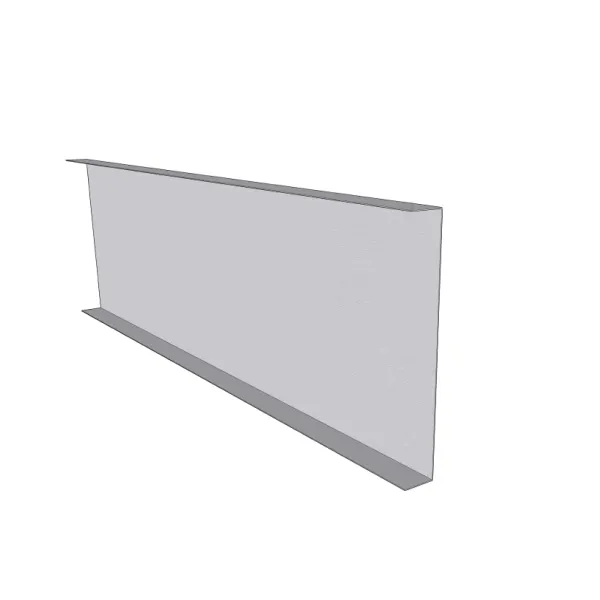
Корпуса должны выдерживать постоянную вибрацию., воздействие негабаритного материала, и агрессивные среды. Общие материалы включают:
- Углеродистая сталь с эпоксидным покрытием. – экономично для сухих, некоррозионные применения.
- Нержавеющая сталь (304/316) – требуется для мокрого досмотра, химическое воздействие, или пищевые процессы.
- Полиуретановые или резиновые накладки – снизить шум и истирание внутренних поверхностей.
Корпус должен быть модульным, чтобы обеспечить легкий доступ при замене ситового полотна.. Компания Haiside разрабатывает корпуса с секциями панелей на болтах и быстросъемными защелками., минимизация времени простоя при обслуживании.
Эффективность уплотнения
В хорошем корпусе используются непрерывные резиновые уплотнительные ленты на всех стыках и вокруг смотровых дверей.. Системы отрицательного давления с фильтрацией рекомендуются для очень мелкой пыли. (ниже 10 микроны). Оцените эффективность уплотнения путем измерения уровня неорганизованной пыли в сопоставимых установках..
…
Более подробную информацию о выборе пылезащитных чехлов и защитных устройств для виброгрохотов см., пожалуйста, нажмите здесь: https://www.hsd-industry.com/news/selecting-dust-enclosures-and-safety-guards-for-vibrating-screens/