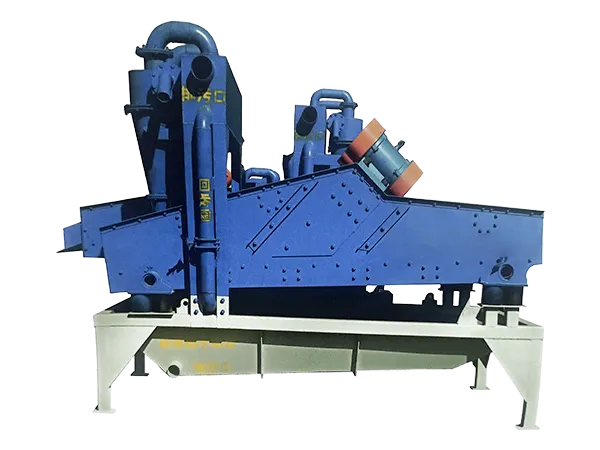
Para cualquier ingeniero que trabaje con maquinaria rotativa, ya sea en equipos de construcción, turbinas de viento, o robótica industrial: comprender la capacidad de carga de los rodamientos no es solo un detalle técnico; es la base de un diseño confiable. Seleccionar el rodamiento incorrecto o juzgar mal las cargas aplicadas puede provocar fallas prematuras, costoso tiempo de inactividad, o incluso falla estructural catastrófica. Este artículo desglosa los tres componentes fundamentales de la carga., Los factores que influyen en la capacidad., y un marco de selección práctico. También destacaremos cómo LYMC, un fabricante confiable de rodamientos giratorios de alta precisión, diseña sus productos para satisfacer los exigentes requisitos de carga con un rendimiento comprobado.
Comprensión de los tres tipos de carga en un rodamiento giratorio
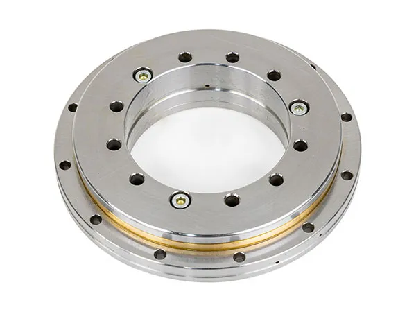
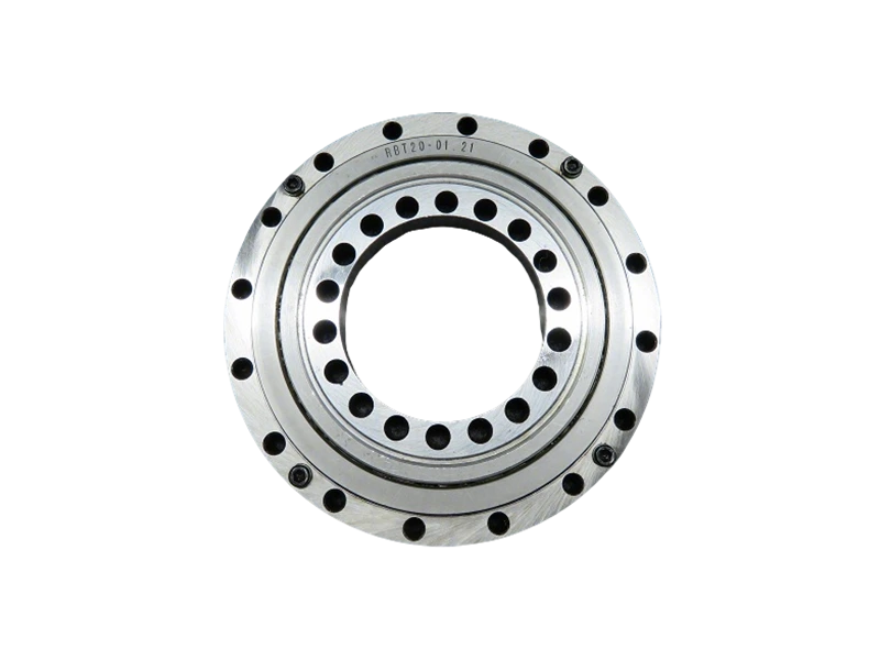
Un rodamiento giratorio debe soportar simultáneamente cargas axiales., cargas radiales, y momentos de inclinación. Cada tipo impone diferentes distribuciones de tensiones en las pistas de rodadura y los elementos rodantes., y las aplicaciones del mundo real rara vez ven una carga pura; la mayoría involucra combinaciones de los tres.
Carga axial (Carga de empuje)
La carga axial actúa paralela al eje de rotación del rodamiento.. en una grua, por ejemplo, El peso de la pluma y la carga levantada producen una fuerza axial hacia abajo.. Los rodamientos giratorios son generalmente más fuertes en la dirección axial., pero la magnitud y dirección (hacia arriba vs.. hacia abajo) debe ser considerado. LYMC diseña perfiles de canalización para maximizar la distribución de carga axial, Reducir la tensión de contacto en el borde de los rodillos..
Carga radial
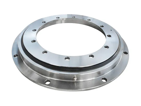
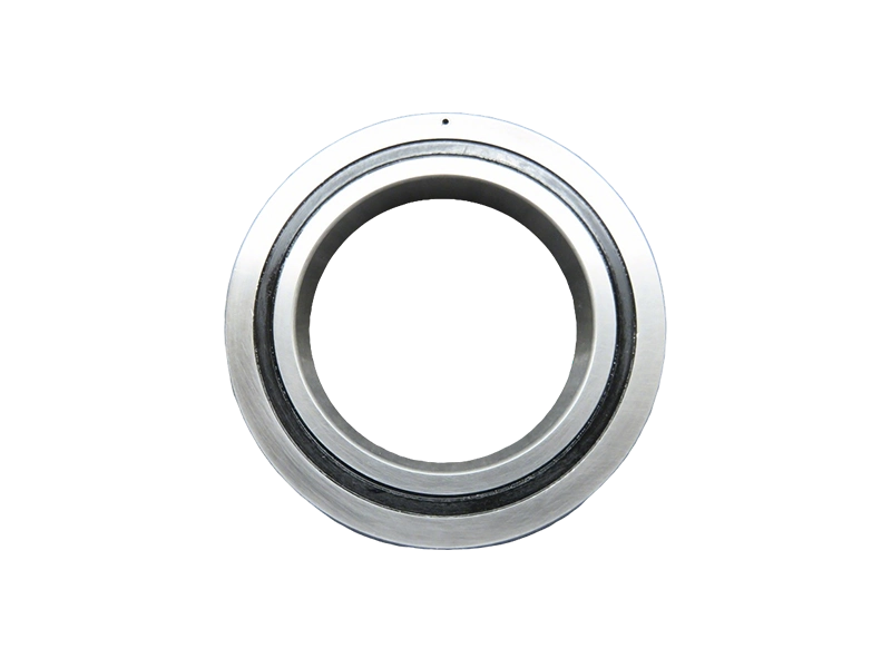
La carga radial actúa perpendicular al eje de rotación.. En aplicaciones horizontales como mesas divisorias o sistemas de giro de excavadoras., Las fuerzas radiales provenientes de cargas laterales o reacciones de engranajes pueden ser significativas.. Aunque los rodamientos giratorios no están optimizados para cargas puramente radiales, Los diseños modernos con elementos de rodillos cruzados o bolas de contacto de cuatro puntos proporcionan una capacidad radial moderada.. Los ingenieros deben verificar que el componente radial no exceda la clasificación del rodamiento..
Momento de inclinación (Carga de momento)
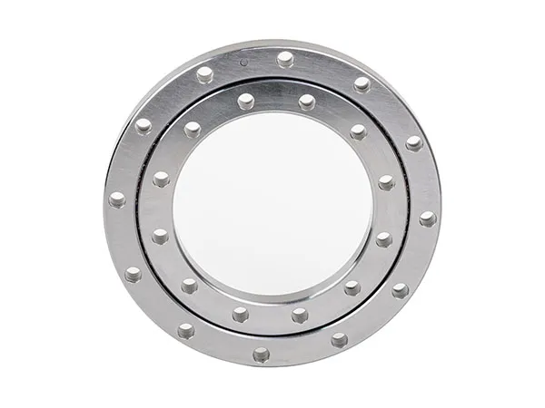
El momento de inclinación es a menudo el tipo de carga más crítico para los rodamientos giratorios.. Resulta de cargas axiales compensadas o fuerzas laterales que crean un par alrededor del centro del rodamiento.. Por ejemplo, El brazo de una grúa torre crea un gran momento de vuelco que el rodamiento giratorio debe resistir.. La capacidad contra el momento de inclinación generalmente está limitada por la muesca de la pista de rodadura y la vida a fatiga.. Los procesos patentados de tratamiento térmico y rectificado de pistas de rodadura de LYMC mejoran la capacidad de momento hasta en 15% en comparación con los puntos de referencia estándar de la industria.
Factores clave que influyen en la capacidad de carga
La capacidad de carga no es un número fijo; depende de las propiedades del material, geometría, lubricación, y condiciones de funcionamiento. Comprender estos factores ayuda a los ingenieros a evitar el exceso de especificaciones (desperdiciar) o subespecificación (riesgo).
…
Para obtener más información sobre la capacidad de carga de los rodamientos giratorios que todo ingeniero debe conocer, por favor haga clic aquí:https://www.mcslewingbearings.com/a/news/slewing-load-capacity.html