In many mechanical equipment, the spindle bearings are mostly angular contact ball bearings. Compared with other types of spindle bearings, this kind of bearing has the advantage of being able to carry both radial and axial forces. However, the heating problem is related to other types of spindle bearings. Spindle bearings still exist, so is it normal for angular contact ball bearings to heat up? What is the cause of heat generation?

Is it normal for angular contact ball bearings to heat up?

Machine Tool Bearings

Under normal circumstances, as long as the temperature is within the range of use requirements, the heating of angular contact ball bearings is a normal phenomenon, especially when used in a spindle environment that rotates at high speeds, heating is inevitable, and friction is the main reason for the heating of angular contact ball bearings. reason.

The friction of angular contact ball bearings is very complex, mainly including differential sliding friction on the channel contact surface, spin sliding friction, friction caused by external loads, and viscous friction of lubricating oil, etc. Among them, the interactive influence of frictional heating and heat-induced load It has a greater impact on the heat generation of the bearing.

During the operation of angular contact ball bearings, thermally induced load and frictional heating interact with each other. The bearing generates frictional heating under the action of radial load, axial load, initial preload force and rotational speed, which increases the bearing temperature and generates heat-induced load. The thermally induced load affects the frictional heat of the bearing, causing the bearing temperature to further increase until the bearing temperature tends to a stable state.

For more detailed information about the heating of angular contact ball bearings, please click here: https://www.lkwebearing.com/news-center/angular-contact-ball-bearing-heats-up.html

Because there is clearance in angular contact ball bearings, the inner and outer rings will move relative to each other under load, which will reduce the rigidity of the bearing. In order to reduce vibration, preloading is often used when installing angular contact ball bearings to eliminate the original load. clearance.

Method of preloading angular contact ball bearings

The preloading methods of angular contact ball bearings include radial preloading and axial preloading.

1. Radial preload

Radial preloading is usually achieved by expanding the inner ring of the bearing, or by moving the axial position of the inner tapered hole of the bearing to achieve preloading.

2. Axial preload

Commonly used axial preloading methods include grinding washer thickness, adjusting inner and outer spacer thickness, spring preloading, narrowing inner and outer rings, screw cover adjustment, and thrust ring adjustment.

(1) Method of adjusting the thickness of inner and outer spacers

Preloading is achieved by adjusting the thickness of the inner and outer spacers. Due to the thickness of the spacers, a preload force is generated between the inner and outer rings of the angular contact ball bearing.

(2) Grinding washer thickness method

The inner and outer rings of the bearing are relatively moved to achieve preloading. When the thickness of washer 1 is smaller, the preloading force of the angular contact ball bearing is greater; when the thickness of washer 2 is smaller, the preloading force is smaller.

(3) Narrowing the inner and outer rings

Preloading is achieved by grinding the inner or outer rings of bearings used in pairs. To narrow the inner ring, the two inner rings are pressed relatively tightly during assembly, and the bearing can produce preload; to grind the outer ring to narrow the assembly, When the two outer rings are relatively compressed, the bearing can be preloaded.

For more detailed information on the preloading method and measurement of angular contact ball bearings, please click here:https://www.lkwebearing.com/news-center/angular-contact-ball-bearing-preload-determination.html

The Ford 4000 tractor is a popular model that has been used in agriculture for many years. If you’re looking for information about the clutch disc for the Ford 4000 tractor, it’s important to consider that specifications and availability may vary depending on the tractor’s year of manufacture and any modifications that may have been made to it over time.

Ford 4000 tractor clutch plate selection

Size and Specifications

The clutch disc size and specifications may vary, so it’s crucial to know the exact model year and variant of the Ford 4000 tractor you have. Tractor parts suppliers and manufacturers provide specifications for their products, and you should match these to the requirements of your specific tractor.

Material and Construction

Clutch discs are typically made of friction material, and the quality of this material can impact the overall performance and longevity of the clutch. Some clutch discs may have specific features, such as a spring center or a solid hub. Ensure that the replacement clutch disc matches the original specifications.

Purchase from Reputable Suppliers

When looking for a replacement clutch disc, it’s advisable to purchase from reputable tractor parts suppliers or dealers. They often have knowledgeable staff who can guide you in selecting the right part based on your tractor’s specifications.

For more detailed information on how to choose a Ford 4000 tractor clutch disc, please click here: https://www.syclutch.com/personal/ford-4000-tractor-clutch-disc-selection.html

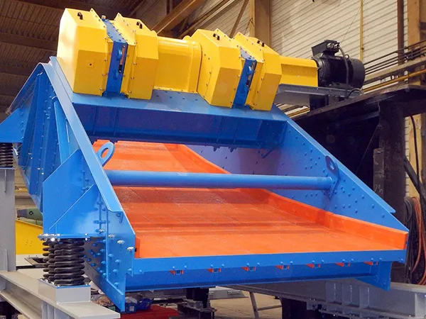
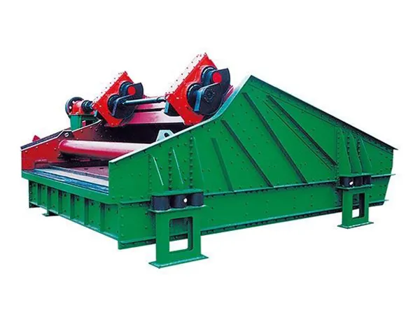
Calculating the motor power of a vibrating screen involves several factors, including the type of screen, the amplitude and frequency of vibration, the size and shape of the screen deck, and the material being processed. Here is a general approach to calculate the motor power for a vibrating screen:

Determine the Screen Type

High Frequency Dehydration Vibrating Screen

Vibrating screens can be classified into horizontal, inclined, or banana screens. The type of screen will affect the calculation.

Identify Screen Parameters

Amplitude (A): The maximum displacement of the screen deck from its rest position.

Frequency (f): The number of oscillations or cycles per unit of time.

Calculate Vibrating Mass

Linear vibrating screen

The vibrating mass on the screen can be calculated using the formula:

m=Weight of the screen deck/g

where g is the acceleration due to gravity.

Calculate Excitation Force

The excitation force can be calculated using the formula:

F=m⋅A⋅(ω)²

where ω=2πf.

Determine Motor Power

The motor power (P) can be calculated using the formula:

P=F⋅v/ 1000

​where v is the vibrating speed (usually in m/s).

For more detailed information on how to calculate the vibrating screen motor power, please click here: https://www.hsd-industry.com/news/vibrating-screen-motor-power-calculation/

Angular contact ball bearings are a type of rolling-element bearing designed to handle both axial and radial loads by supporting the shaft in both axial and radial directions. Here’s a guide covering sizes, types, applications, and general pricing information.

Angular contact ball bearings guide

H70C-ACP4 Ultra High Speed Series

Sizes

Angular contact ball bearings come in various sizes, and their dimensions are typically specified by the bore diameter (d), outside diameter (D), and width (B). Common size ranges include:

  • Bore Diameter (d): From a few millimeters to several hundred millimeters.
  • Outside Diameter (D): Typically ranges from tens of millimeters to several meters.
  • Width (B): Varies depending on the specific design and application requirements.

Sizes are usually standardized, and specific dimensions can be found in catalogs provided by manufacturers.

Types

Single-Row Angular Contact Ball Bearings:

  • Suitable for carrying axial loads in one direction and limited radial loads.
  • Can be paired to accommodate axial loads in both directions.

Double-Row Angular Contact Ball Bearings:

  • Consist of two rows of balls separated by a central rib.
  • Capable of handling higher radial and axial loads.

More detailed information about the Angular Contact Ball Bearing Guidelines can be found here: https://www.lkwebearing.com/news-center/angular-contact-ball-bearings-guide.html

Currently, the commonly used matched bearings for machine tool spindles are angular contact ball bearings. Usually, complete sets of matched bearings are used. In some cases, non-complete sets of angular contact ball bearings may be used for universal matching. However, universal matching faces inconsistent accuracy. , inconsistent ruler time, inconsistent angle, etc., what are the universal matching requirements for angular contact ball bearings? And how to improve the matching accuracy? The following editor has compiled relevant content for you, hoping to be helpful to you.

What are the universal matching requirements for angular contact ball bearings?

PX Sealed 4 Point Contact Ball Bearing Series

When pairing angular contact ball bearings, in addition to relying on high-precision equipment during the production process to directly ensure the mutual differences in the inner and outer diameter groove dimensions, groove curvature, and groove position, the contact angle, the mutual difference in the inner and outer diameter dimensions, and the protrusion amount must also be ensured. Wait for the request.

1. Contact angle

The contact angle of universal matched angular contact ball bearings directly affects the stress state of the bearing under working conditions. The contact angle difference between two matched sets of bearings should be as small as possible. Generally, the contact angle difference between precision and ultra-precision matched bearings is About 1°. When selecting, the contact angle is controlled by controlling the radial clearance according to the relationship between the radial clearance and the contact angle.

cosβ= 1-Y/2 (Re+ Ri-2Rw)

In the formula:

β – contact angle

Y – radial clearance

Re – outer ring groove curvature radius

Ri – inner ring groove curvature radius

Rw – steel ball radius

As can be seen from the above formula, the difference in curvature radius of the inner and outer ring grooves can be effectively controlled during processing. Using the same set of steel balls for assembly can reduce the impact on the contact angle. Controlling the contact angle by fine-tuning the radial clearance can improve the angular contact Universal matching accuracy of ball bearings.

More detailed information on the general fit requirements for angular contact ball bearings can be found here: https://www.lkwebearing.com/news-center/angular-contact-ball-bearing-matching-requirements.html

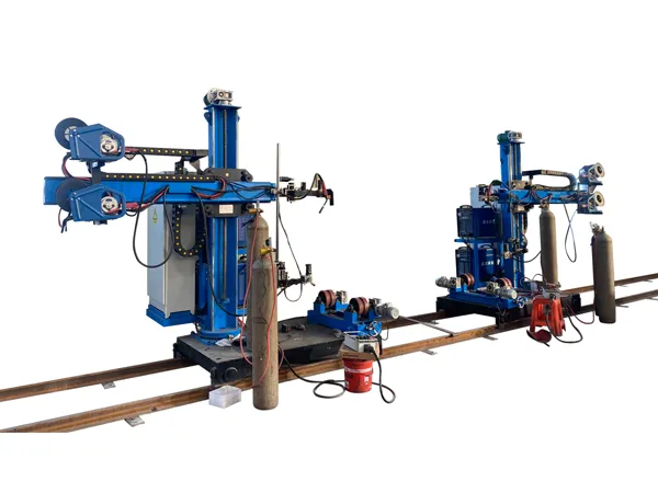
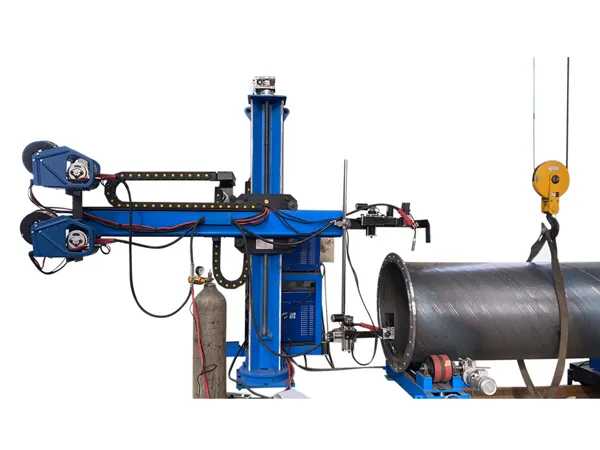
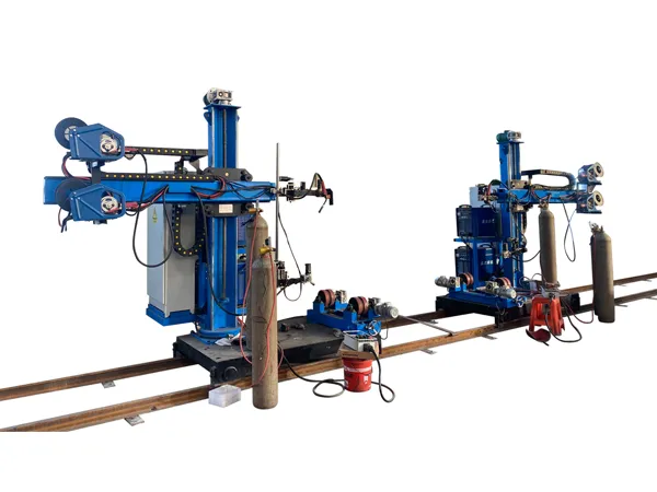
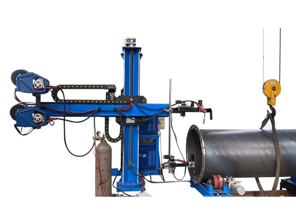
A welding positioner is a specialized piece of equipment used in welding applications to position a workpiece in the optimal orientation for welding. It helps welders to achieve better precision, accessibility, and efficiency in the welding process. The positioner allows for the rotation or tilting of the workpiece, making it easier for the welder to reach all necessary angles without having to reposition themselves.The installation of a welding positioner involves several key steps to ensure its proper setup and safe operation.

Welding positioner installation process

welding positioner

1. Site Preparation

Choose a location for the welding positioner that provides sufficient space for safe operation and easy access. Ensure that the floor is level and can support the weight of the positioner.

2. Unpacking and Inspection

Carefully unpack the welding positioner and inspect it for any shipping damage. Check for all the components listed in the user manual.

3. Positioner Placement

Place the welding positioner in the desired location. If it is a large or heavy unit, use appropriate lifting equipment to move it into place.

4. Leveling

Use a level to ensure that the welding positioner is perfectly level. This is critical for accurate and stable positioning during welding.

welding positioner

5. Securing the Positioner

Once leveled, secure the welding positioner to the floor using appropriate anchors or fasteners. This step is essential for stability and safety during operation.

6. Power Connection

Connect the welding positioner to the power source according to the manufacturer’s specifications. Ensure that the power supply meets the equipment requirements.

For more detailed information about the welding positioner installation process, please click here: https://www.bota-weld.com/en/a/news/welding-positioner-installation-process.html

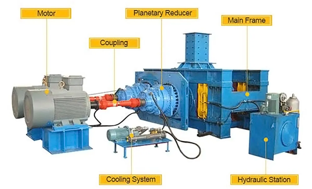
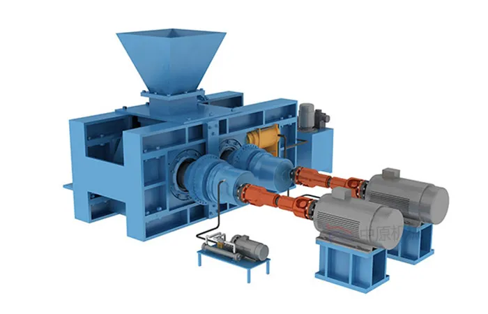
A ball press machine, also known as a briquette press or pellet press, is a device that compacts powder or granular material into larger, more manageable forms. These machines are commonly used in various industries for shaping materials into uniform, dense balls or briquettes, typically for ease of storage, transportation, or further processing.

Components of a Ball Press Machine

ball press machine

Hopper:

The hopper is where the raw material, such as powder or fine particles, is loaded into the machine.

Auger or Screw Conveyor:

An auger or screw conveyor transports the raw material from the hopper to the compression chamber.

Compression Chamber:

The compression chamber is where the actual compaction process takes place. The raw material is compressed into a specific shape, often a ball or cylindrical form, using mechanical pressure.

Rollers or Dies:

Rollers or dies inside the compression chamber help shape and compress the material into the desired form.

Hydraulic or Mechanical System:

The machine is equipped with a hydraulic or mechanical system that provides the force necessary for the compaction process.

Control Panel:

The control panel allows operators to adjust and control parameters such as pressure, temperature, and the speed of the machine.

Operation of a Ball Press Machine

ball press machine

Loading:

The raw material is loaded into the hopper.

Transportation:

The auger or screw conveyor moves the material from the hopper to the compression chamber.

For more detailed information about what is a briquetting machine, please click here: https://www.zymining.com/en/a/news/what-is-a-ball-press-machine.html

A harmonic reducer, also known as a strain wave gear or harmonic drive, is a type of precision gear mechanism used for speed reduction in various applications, particularly in robotics, aerospace, and industrial automation. The harmonic reducer bearing is known for its compact size, high torque density, and accuracy. It operates on the principle of elastic deformation to achieve gear reduction.Here’s an introduction to the main components and working principles of a harmonic reducer.

Components

harmonic reducer bearing

Wave Generator (Input Shaft): The wave generator is the input component that generates a wave-like motion, typically through an eccentric cam. This wave motion is transmitted to the flexspline.

Flexspline (Flexible Circular Spline): The flexspline is a thin, flexible, and toothed circular disc that deforms under the influence of the wave generator’s motion. It is the output element of the system.

Circular Spline (Fixed Outer Gear): The circular spline is a rigid, toothed ring that meshes with the flexspline. It is fixed in place and provides the necessary reaction to the flexspline’s deformation.

Working Principle

harmonic reducer bearing

Elastic Deformation: The key principle of a harmonic reducer is the elastic deformation of the flexspline. As the wave generator rotates, it creates a wave motion in the flexspline, causing it to deform. The deformation allows the teeth on the flexspline to engage with the teeth on the circular spline.

Zero-Backlash: One of the advantages of harmonic reducers is their minimal backlash. Backlash is the play or clearance between gear teeth. In a harmonic drive, the meshing of teeth is achieved through elastic deformation, reducing or eliminating backlash.

High Torque Density: Harmonic reducers are known for their high torque density, meaning they can provide significant torque output in a compact and lightweight design. This makes them suitable for applications where space and weight are critical factors.

For more detailed information on the working principle of harmonic reduction bearings, please click here: https://www.boyingbearing.com/en/a/news/working-principle-of-harmonic-reducer-bearings.html

Mobile healthcare shelving plays a crucial role in medical institutions by contributing to the efficiency, organization, and accessibility of medical supplies, equipment, and records.

The roles of mobile healthcare shelving in medical institutions

Mobile healthcare shelving

Space Optimization

Mobile shelving systems are designed to maximize the use of available space. In healthcare settings where space is often limited, these shelving units can be compacted or expanded as needed, allowing for better space utilization.

Organization and Storage

Mobile shelving provides a systematic and organized way to store medical supplies, documents, and equipment. It helps in categorizing items, making it easier for healthcare professionals to locate and access what they need promptly.

Flexibility and Adaptability

The mobility of these shelving units allows for easy reconfiguration of storage space. This adaptability is especially valuable in healthcare environments where storage needs may change frequently due to evolving equipment requirements or changes in the volume of supplies.

Infection Control

Mobile healthcare shelving systems are often designed with materials and features that facilitate easy cleaning and maintenance. This is crucial in medical institutions where maintaining a clean and sterile environment is essential for infection control.

Mobile healthcare shelving

Secure Storage of Sensitive Items

Mobile shelving units can include locking mechanisms to secure sensitive medical supplies, pharmaceuticals, or confidential patient records. This helps in maintaining the security and privacy of critical items and information.

Efficient Retrieval of Supplies

With mobile shelving, healthcare professionals can access supplies quickly, reducing the time spent searching for items. This efficiency is particularly important in emergency situations where timely access to medical equipment and supplies can be critical.’

For more detailed information about the role of mobile medical shelves in medical institutions, please click here: https://www.etegreen.com/en/a/news/the-role-of-mobile-healthcare-shelving-in-medical-institutions.html