Proper tensioning of vibrating screen mesh is often underestimated in its impact on overall screening performance. Yet, for operations handling bulk materials—from aggregate to minerals—the tension applied to the screen cloth directly determines throughput accuracy, wear life, and operating costs. When tension is too loose, the screen flexes excessively, leading to premature fatigue, blinding, and inefficient particle separation. When over-tightened, the mesh may crack or distort, reducing screening area. In either case, measurable losses occur. This article examines the quantitative advantages of maintaining correct screen tension, drawing on field data and engineering principles, and explains how Haiside tensioning systems help operators achieve consistent, verifiable results.

1. The Direct Impact on Screening Efficiency and Throughput

The primary function of a vibrating screen is to separate particles by size. Screen tension plays a critical role in how effectively the mesh transmits vibration to the material bed. A properly tensioned screen maintains a uniform amplitude across its surface, ensuring that each particle receives the same acceleration and stratification force.

Quantifying Particle Separation Accuracy

Studies have shown that a tension deviation of just 10% from optimal can reduce screening efficiency by 15–20%. Loose screens allow the mesh to flutter independently of the screen deck, creating localized areas of reduced vibration. Oversized particles may pass through momentarily stretched openings, while near-size particles become trapped, increasing pegging. Conversely, a properly tensioned screen from Haiside maintains consistent opening dimensions, resulting in tighter cut-point control. In a typical 2-deck operation, proper tension can improve oversize recovery by 8–12% and reduce misplaced fines in oversize product.

How Tension Affects Material Flow Rate

Throughput is directly linked to the open area available for material passage. When a screen is loose, it bows under the load, reducing the effective screening surface. Over multiple cycles, this bowing increases, further restricting flow. Proper tensioning ensures the mesh remains flat and taut, maximizing open area. Field measurements indicate that restoring correct tension can increase mass flow by 6–10% on the same screen deck without changing stroke or speed. For a plant processing 500 tons per hour, this translates to an additional 30–50 tons per hour of correctly sized product.

2. Extended Screen Life – Reducing Replacement Frequency
Cooperation Customer

Screen cloth is a consumable with significant cost implications. Many operators accept a short life as normal, but the failure mode is often linked to improper tension rather than inherent wear. A screen that is too loose undergoes repeated flexing at the tensioning hooks and around the support bars. This cyclic bending stress causes fatigue cracks that propagate quickly, leading to sudden failure.

…

Click here for more details on the measurable benefits of proper vibrating screen tensioning: https://www.hsd-industry.com/news/measurable-benefits-of-proper-vibrating-screen-tensioning/
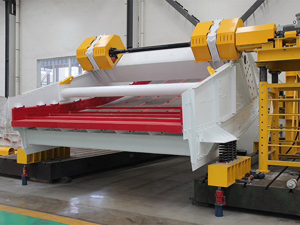
Heavy-duty vibrating screens are the backbone of material processing in mining, aggregates, and industrial sectors. Yet structural failures—cracks in side plates, broken beams, or weld fatigue—remain costly and dangerous. These failures not only halt production but also risk worker safety and escalate maintenance budgets. Understanding why these failures occur and how to prevent them is critical for any operation that depends on consistent screening performance. This article examines the root causes of structural breakdowns and presents proven engineering strategies, including the advanced approaches adopted by leading manufacturers like Haiside, to ensure long-term reliability.

Understanding Structural Failures in Heavy-Duty Vibrating Screens

Structural failures typically manifest in three forms: fatigue cracking, resonance-induced damage, and material degradation. Fatigue cracking, the most common, develops over millions of cycles due to cyclic stress concentrations at weld joints, bolt holes, or geometric transitions. Resonance occurs when the operating frequency aligns with a natural frequency of the structure, amplifying vibration amplitudes beyond design limits. Material degradation can result from corrosion, abrasion, or substandard steel grades that lack sufficient impact toughness.

Root Causes Explained

  • Improper design margins: Many failures stem from inadequate safety factors in the structural frame, particularly at the support beams and cross members.
  • Poor weld quality: Incomplete penetration, slag inclusions, or lack of preheating in thick sections create crack initiation sites.
  • Overlooking dynamic loads: Static calculations miss the amplified forces from eccentric masses and material impacts—real loads can exceed static estimates by 3–5 times.
  • Environmental factors: Moisture, chemical exposure, and temperature extremes accelerate fatigue crack growth.

Key Design Strategies to Prevent Structural Failures

Preventing failures starts at the design stage with a focus on fatigue life optimization. Finite element analysis (FEA) is now standard to simulate stress distribution under dynamic loading. Critical areas such as the discharge end, feed box, and side plate transitions must be reinforced. Haiside engineers, for example, use FEA to identify high-stress zones and apply generous radii, tapered transitions, and ribbed stiffeners to reduce stress concentration factors.

…

For more detailed information on preventing structural failures in heavy-duty vibrating screens, please click here: https://www.hsd-industry.com/news/avoiding-structural-failures-in-heavy-duty-vibrating-screens/

Proper lubrication is the lifeblood of any slewing bearing, directly influencing its operational lifespan, load capacity, and overall reliability. Without a well-planned lubrication strategy, even the highest-quality slewing bearing can suffer from premature wear, increased friction, and eventual failure. This article, informed by decades of industry experience from LYMC, outlines the critical best practices for lubricating slewing bearings to ensure long-term reliability in demanding applications such as construction equipment, wind turbines, and material handling systems.

Understanding Lubrication Fundamentals for Slewing Bearings

Slewing bearings operate under unique conditions, combining both rotational and oscillating movements while supporting large axial and radial loads. The lubricant must not only reduce friction between rolling elements and raceways but also protect against corrosion, dissipate heat, and seal out contaminants. The two primary lubrication methods are grease lubrication and oil lubrication. Grease is the most common choice due to its simplicity, reduced leakage, and ability to act as a seal. Oil lubrication, while offering better cooling and high-speed performance, is typically reserved for specialized high-speed or extreme-temperature environments.

Key Functions of Lubrication

  • Friction Reduction: A continuous lubricant film separates rolling elements from raceways, preventing metal-to-metal contact.
  • Wear Protection: Additives in the lubricant form a protective layer that minimizes abrasive and adhesive wear.
  • Corrosion Prevention: The lubricant barrier excludes moisture and contaminants that cause rust and pitting.
  • Heat Dissipation: Lubricant carries away frictional heat, maintaining stable operating temperatures.
  • Contaminant Exclusion: Thickened grease helps seal the bearing against dust, dirt, and water ingress.

Selecting the Right Lubricant for Optimal Performance

Choosing the correct lubricant is a critical decision that depends on operating conditions, load spectrum, ambient temperature, and rotational speed. LYMC recommends evaluating three key parameters:

Viscosity and Base Oil

The base oil viscosity must be sufficient to maintain an elastohydrodynamic (EHD) film under load. For most slewing bearing applications, an ISO VG 220 to 680 grade grease is typical. Higher loads and slower speeds call for higher viscosity. Synthetic base oils (e.g., PAO, silicone) offer better thermal stability and longer life in extreme temperatures.

Thickener Type

Lithium complex thickeners are widely used due to their good mechanical stability and water resistance. Polyurea greases excel in high-temperature and high-speed applications. Aluminum complex thickeners provide excellent water resistance for outdoor or marine environments.

…

For more detailed information on best practices for the long-term lubrication reliability of slewing bearings, please click here: https://www.mcslewingbearings.com/a/news/slewing-lubrication-guide.html

Selecting a slewing bearing for heavy machinery such as cranes, excavators, or wind turbines is a critical procurement decision. A poorly performing bearing can lead to downtime, safety hazards, and costly replacements. Before finalizing a purchase, you need to verify that the bearing meets your operational demands. This article provides a systematic approach to test slewing bearing performance, covering key indicators, practical methods, and how to partner with a reliable manufacturer like LYMC to ensure long-term reliability.

Why Pre-Purchase Testing Matters

Slewing bearings are designed to handle combined loads—axial, radial, and moment—under slow or oscillating rotation. Unlike standard rolling bearings, they are often custom-made for specific applications. Testing before purchase helps you avoid mismatched specifications, premature failures, and unexpected costs. A thorough pre-purchase evaluation should include dimensional checks, material verification, and functional simulation.

Key Performance Indicators to Test

1. Rotational Accuracy and Running Torque

Measure the starting torque and running torque under no-load and light-load conditions. Excessive torque indicates poor raceway finishing or improper internal clearance. Use a torque wrench or a dedicated test rig. For most applications, the running torque should be smooth and consistent without sudden spikes. LYMC performs torque measurement on every bearing to ensure compliance with ISO specifications.

2. Axial and Radial Runout

Runout directly affects the alignment of your equipment. Mount the bearing on a test fixture and rotate it slowly while measuring axial and radial displacement with dial indicators. Permissible runout depends on the application; for precision turntables, it may be less than 0.1 mm, while for excavators, up to 0.5 mm can be acceptable. Always compare measured values against the manufacturer’s declared tolerance.

3. Hardness and Case Depth

The raceway surface hardness typically ranges from HRC 55–62 for induction-hardened slewing bearings. Use a portable hardness tester on a small area (with manufacturer’s consent) or request a test coupon from the same production batch. The case-hardened depth should be at least 2–3 mm for heavy-load applications. Inadequate hardness leads to rapid wear and plastic deformation.

…

Click here for more detailed information on how to test the performance of a slewing bearing before purchase: https://www.mcslewingbearings.com/a/news/test-slewing-bearing.html

When standard slewing bearings fail to meet the unique demands of specialized machinery, customization becomes not just an option but a necessity. Whether the application involves extreme loads, unusual mounting configurations, harsh environmental exposure, or precise motion control, tailored solutions ensure reliability and performance. Understanding the full spectrum of customization possibilities empowers engineers and procurement professionals to make informed decisions that reduce downtime and extend service life. This article examines the critical customization parameters, industry-specific adaptations, and how LYMC delivers engineered solutions for the most challenging rotating systems.

Why Standard Slewing Bearings Fall Short in Special Applications

Off-the-shelf slewing bearings are designed for typical load profiles, rotational speeds, and environmental conditions. However, special applications—such as radar antenna bases, underwater robotic arms, or high-speed packaging turntables—impose requirements that exceed standard catalogs. Common limitations include:

  • Insufficient load capacity for axial, radial, or moment loads acting simultaneously.
  • Unsuitable mounting interfaces (bolt patterns, pilot diameters not matching customer equipment).
  • Inadequate sealing against contaminants like dust, water, chemicals, or extreme temperatures.
  • Non-optimal internal clearance or preload for precision positioning or torque consistency.
  • Incompatible lubrication systems for continuous operation or maintenance-free cycles.

Customization addresses these gaps by modifying geometry, materials, and auxiliary features to align perfectly with the machine’s operating envelope.

Key Customization Parameters for Slewing Bearings

Every custom slewing bearing begins with a thorough analysis of the application’s mechanical and environmental demands. Below are the primary parameters that can be tailored.

Dimensional and Geometric Modifications

Beyond standard diameters and cross-sections, custom bearings can feature non-circular raceways, asymmetric race profiles, or integrated flanges. The pitch circle diameter, number and size of mounting holes, and overall height can be adjusted to fit existing structures without redesigning surrounding components. LYMC offers flexibility in tolerances to accommodate thermal expansion or high-speed rotation.

…

Click here for more detailed information on customization options for slewing bearings designed for special applications: https://www.mcslewingbearings.com/a/news/slewing-bearing-custom-options.html

The clearance of a slewing bearing directly determines the operational stability, load distribution, and service life of an excavator. An improper clearance can lead to excessive vibration, accelerated wear, or even catastrophic failure of the superstructure. For maintenance teams, equipment dealers, and fleet managers, understanding what constitutes the ideal clearance is not merely technical—it is a financial decision affecting downtime and repair costs. This article explores the definition, influencing factors, industry-recommended values, and how to verify the correct clearance for your excavator. We also highlight how LYMC applies precision engineering to deliver bearings that meet or exceed OEM specifications.

What Is Slewing Bearing Clearance?

Slewing bearing clearance, often referred to as axial or radial play, is the measured gap between the rolling elements and the raceways under a defined load condition. For excavators, the clearance is critical because the bearing must handle combined axial, radial, and tilting moment loads during digging, swinging, and lifting operations.

Types of Clearance

  • Initial clearance – the clearance before installation, as manufactured. This is what bearing suppliers specify on datasheets.
  • Mounting clearance – the clearance after the bearing is installed in the excavator, affected by housing fit and bolt preload.
  • Operating clearance – the clearance under actual working loads and temperature conditions. Thermal expansion and elastic deformation change the clearance.

For excavator slewing bearings, the most commonly referenced parameter is the axial internal clearance measured under a standard preload (typically 500–1000 N). The ideal value is a balance: enough clearance to prevent jamming from thermal expansion, but not so much that it causes slop and uneven load distribution.

Factors That Determine the Ideal Clearance

Selecting the correct clearance requires evaluating several operating conditions. No single value fits all excavators.

Load Magnitude and Direction

Excavators experience high tilting moments during digging. A bearing that is too loose will allow excessive tilting, accelerating raceway and ball wear. Conversely, a bearing that is too tight may induce high internal stress, reducing fatigue life. For standard excavators (20–50 ton class), axial clearance typically falls between 0.04 mm and 0.12 mm (40–120 microns) for single-row ball slewing rings, and 0.08–0.20 mm for cross-roller types.

Operating Speed and Temperature

Excavator slewing speeds are low (usually 1–5 rpm), so heat generation is modest. However, in hot climates or continuous heavy digging, the bearing temperature can rise 15–30°C above ambient. Thermal expansion of the raceways reduces clearance. Engineers often specify an initial clearance at the upper end of the tolerance band when the excavator will work in high-temperature environments.

…

To learn more about the ideal clearance for excavator slewing bearings, please click here for detailed information: https://www.mcslewingbearings.com/a/news/bearing-clearance-guide.html

When evaluating tunnel formwork options, the allure of a low upfront price can be powerful. However, what appears to be a cost-saving decision often masks a cascade of hidden risks that can derail budgets, timelines, and structural integrity. This article dissects the real cost of cheap tunnel formwork—from safety liabilities and material failures to project delays—and explains why partnering with a trusted manufacturer like Gaofei is not an expense but an investment in predictable, high-quality outcomes.

1. The Illusion of Savings: Initial Price vs. Total Cost of Ownership

The cheapest formwork systems typically cut corners in material grade, manufacturing precision, and quality control. While the purchase price may be 30–50% lower than reputable brands, the total cost of ownership over the life of a project often surpasses that of premium systems. Key hidden costs include:

  • Frequent Repairs and Replacements: Low-grade steel or aluminum warps under repeated concrete pressure, leading to panel deformation. This forces premature replacement or expensive on-site rework. Gaofei uses high-strength alloys that maintain dimensional stability for hundreds of cycles.
  • Increased Labor Hours: Ill-fitting panels require more time to align, brace, and clamp. Every extra minute on labor multiplies across crews and shuttering cycles, eroding the supposed savings.
  • Hidden Logistics Expenses: Cheap formwork often arrives with incomplete hardware, missing bolts, or poor packaging. The cost of rush orders, replacement parts, and downtime can quickly exceed the initial discount.

2. Safety Hazards: The Non-Negotiable Risk

Tunnel formwork supports thousands of tons of wet concrete and live loads. A failure does not just cost money—it endangers lives. Cheap systems introduce multiple safety vulnerabilities:

Material Fatigue and Buckling

Formwork from discount manufacturers often uses thinner plates and lower-grade welds. Over repeated use, micro-cracks propagate into critical failures. Gaofei’s formwork undergoes rigorous load testing and meets international safety standards like BS 5975 and EN 12812.

Unstable Anchoring and Connection Points

Inferior locking mechanisms can slip under vibration during concrete placement. Reports of collapse in low-cost systems have been documented in emerging markets, leading to injuries and costly litigation. Gaofei employs precision-machined cam locks with safety redundancies that are 100% inspected before shipment.

3. Schedule Overruns: When Cheap Becomes Costly

A tunnel project’s profitability depends on cycle speed. Cheap formwork introduces chronic delays:

  1. Alignment Troubles: Warped panels require constant shimming and adjustment, adding 15–20% to the cycle time per pour.
  2. Stripping Difficulties: Poor coatings cause concrete adhesion. Stripping takes longer and may damage panels, further slowing the next cycle.

…

Click here for more details on the true cost of cheap tunnel formwork and the hidden risks involved: https://www.gf-bridge-tunnel.com/a/blog/cheap-tunnel-formwork-risks.html

In the production of precast concrete tunnel segments, cracking remains one of the most persistent quality challenges. Even minor hairline cracks can compromise structural integrity, reduce service life, and lead to costly rework. While many factors contribute to cracking—from mix design to curing—temperature management during the molding process is frequently overlooked. This article examines how temperature-controlled tunnel molds offer a systematic solution to prevent cracking, and how Gaofei specializes in engineering such molds to achieve consistent, defect-free outcomes.

Why Cracks Form in Tunnel Molds: The Thermal Gradient Problem

Cracking in concrete tunnel segments is rarely caused by a single factor. However, the most common root cause is an excessive temperature gradient between the core and the surface of the fresh concrete. When concrete hydrates, heat is released internally. In a standard mold without temperature control, the outer layers cool faster while the core remains hot, creating differential expansion and contraction. This thermal stress exceeds the early-age tensile strength of concrete, resulting in cracks.

Additionally, rapid cooling after stripping can introduce shock. Traditional molds made of steel or concrete have high thermal conductivity, but without active control, they amplify temperature differences. Temperature-controlled tunnel molds are designed to maintain a uniform thermal environment, reducing the gradient to within safe limits (typically below 20°C). This single intervention can eliminate up to 80% of early-age cracks observed in field studies.

How Temperature-Controlled Molds Work: Active Thermal Regulation

Integrated Heating and Cooling Systems

Gaofei’s temperature-controlled molds incorporate embedded fluid channels that circulate temperature-regulated water or oil. By adjusting the inflow temperature and flow rate, the mold surface can be precisely heated or cooled to match the curing curve of the concrete. This active regulation ensures that the entire segment cures at a uniform rate, even in large or complex geometries.

…

Click here for more detailed information on using temperature-controlled tunnel molds to prevent cracking: https://www.gf-bridge-tunnel.com/a/blog/prevent-cracking-molds.html

As cities expand underground, subway tunnel construction demands precise, durable, and efficient lining formwork systems. A poorly designed formwork can lead to schedule delays, safety risks, and substandard concrete finishes. This case study examines the critical requirements of tunnel lining formwork for subway expansion projects and demonstrates how Gaofei’s engineered solution delivered measurable improvements in speed, accuracy, and cost control for a major metropolitan transit authority.

Critical Requirements for Subway Tunnel Lining Formwork

Subway expansion projects impose unique constraints: limited access shafts, strict vibration limits near existing structures, and demanding concrete curing cycles. The formwork must be lightweight enough for underground handling, yet rigid to maintain profile tolerances under high pour pressures. Traditional timber or generic steel forms often fail in these conditions, leading to honeycombing or geometric deviations.

Key performance indicators for successful tunnel lining formwork include: repetitive accuracy (achieve consistent cross-section across hundreds of rings), rapid cycle time (stripping and resetting within 4–6 hours), and minimal site welding (to avoid fire hazards and speed assembly). Gaofei’s system was designed from the ground up to address these challenges.

Gaofei Tunnel Lining Formwork System: Design & Innovation

Modular Panel Construction with High-Strength Steel

Gaofei employs a proprietary modular steel panel system that interlocks via tapered wedges—no bolts required. This reduces assembly time by 40% compared to conventional bolted forms. The panels are fabricated from corrosion-resistant Q345B steel, guaranteeing over 500 reuses without dimensional loss.

Integrated Hydraulic Travel and Adjustment

Hydraulic jacks mounted on the base frame allow precise vertical and horizontal adjustment of ±50 mm, compensating for slight tunnel alignment variations. The entire form can travel on embedded rails, eliminating the need for crane repositioning every pour. For the case study project, this feature cut cycle time from 8 hours to 5.5 hours per ring.

…

For more details on the case study regarding tunnel lining formwork for the metro expansion, please click here: https://www.gf-bridge-tunnel.com/a/blog/tunnel-lining-formwork.html

Labor costs consistently represent the single largest controllable expense in tunnel construction projects. For decades, traditional formwork methods have required extensive manual handling, skilled carpenters on-site, and prolonged assembly cycles that drive up both direct wages and project timelines. The introduction of automated tunnel formwork systems has fundamentally shifted this equation. Industry data from multiple large-scale infrastructure projects indicates that switching to an automated system can reduce on-site labor requirements by approximately 40%. This article examines the engineering mechanisms behind that reduction, the operational implications for contractors, and what the investment looks like for a typical mid-size tunnel project, drawing on case experience from Gaofei’s deployment across Asia and the Middle East.

The Core Mechanism of Automation in Tunnel Formwork

Automated tunnel formwork differs from conventional systems primarily in how it handles the three critical phases: positioning, pouring, and striking. Traditional systems rely on a crew of 8-12 workers to manually align steel panels, install tie rods, adjust braces, and later dismantle everything piece by piece. An automated system integrates hydraulic cylinders, electromechanical drives, and a central control unit that moves the formwork as a single rigid assembly.

Hydraulic Self-Stripping and Traveling

In a Gaofei automated tunnel formwork system, the entire formwork arch is mounted on a traveling carriage. After the concrete has cured, the hydraulic system retracts the panels by a pre-set distance – typically 50-80 mm – without any manual intervention. The carriage then moves forward along rails to the next pour position. This single sequence eliminates the need for a separate dismantling crew, crane lifting of panels, and re-assembly. On a typical 300-meter tunnel section, this reduces the number of workers per shift from 12 to 7.

Integrated Concrete Delivery and Vibration

Automated systems often include built-in concrete distribution arms and remote-controlled vibrators. Workers no longer need to manually drag hoses or handle immersion vibrators at height. Instead, one operator controls both the concrete flow and vibration pattern from a safe position, further reducing the crew size and eliminating a common source of safety risk.

Why 40% Labor Reduction Is Realistic

The 40% figure is not an arbitrary benchmark. It emerges from a combination of three measurable factors:

  • Reduced crew size per cycle: Automated striking and traveling cut the number of workers needed for formwork handling by 50-60%.
  • Compressed cycle time: A typical 10-meter pour cycle in conventional formwork takes 24-36 hours (including stripping, cleaning, oiling, re-positioning). Automated systems can reduce this to 12-18 hours, meaning fewer total labor hours per linear meter of tunnel.
  • Lower rework and adjustment: Hydraulic precision ensures consistent alignment, reducing the need for skilled carpenters to correct geometry. Unskilled workers can handle most tasks after brief training.

Data from Gaofei’s project on the Delhi Metro extension showed that the labor input dropped from 1.8 man-hours per cubic meter of concrete to 1.1 man-hours – a 39% reduction, matching the headline figure closely.

…

Click here for more details on how automated tunnel formwork can reduce labor costs by 40%: https://www.gf-bridge-tunnel.com/a/blog/automated-tunnel-labor.html