Welding positioners are essential machinery in the fabrication and welding industry, designed to hold and manipulate workpieces into optimal positions for welding. These devices enhance precision, efficiency, and the overall quality of welds, making them indispensable across various industries including aerospace, automotive, and construction.

Core Functionality of Welding Positioners

Welding positioners

Welding positioners serve multiple key functions that streamline the welding process:

Workpiece Manipulation and Orientation: They manipulate the workpiece’s orientation to allow precise control over the welding process, crucial for achieving high-quality welds.

Secure Holding: They securely hold the workpiece in place, ensuring stability and preventing movement that could compromise the weld’s integrity.

Controlled Movement and Rotation: Positioners enable controlled movement and rotation, essential for accessing different angles and reaching intricate areas for uniform welds.

Fixed Position Maintenance: By maintaining a fixed position relative to the welding torch, positioners ensure consistent weld quality and reduce errors.

Enhanced Efficiency: The ability to manipulate and rotate workpieces enhances the welding process’s efficiency, saving time and resources.

Improved Weld Quality: The optimized welding position provided by positioners contributes to improved weld quality, focusing on desired penetration and fusion for stronger, more reliable welds.

Versatility: Positioners come in various sizes and configurations, catering to different welding applications and making them adaptable across industries.

Working Principles of Welding Positioners

Welding positioners

Welding positioners operate through a combination of secure clamping mechanisms and controlled rotational and tilting movements:

Rotational Movements: They provide controlled rotational movements programmable to adjust speed and direction based on specific welding project requirements.

For more detailed information about the core functions of welding positioner, please click here: https://www.bota-weld.com/en/a/news/welding-positioner-core-functions.html

Submerged Arc Welding (SAW) is a commonly used welding process known for its high efficiency and deep penetration. Operating a submerged arc welding machine requires adherence to specific safety and operational procedures to ensure high-quality welds and prevent accidents.

Submerged arc welding machine operating procedures

 SAW welding

1. Pre-Operational Setup

a. Inspection and Preparation

Check the Equipment: Ensure the welding machine, power source, and wire feeder are in good working condition. Inspect cables, connections, and the welding gun for any damage.

Clean the Workpiece: Ensure the surfaces to be welded are clean, free of rust, oil, dirt, or other contaminants that may affect weld quality.

Select Proper Filler Wire: Choose the appropriate wire electrode based on the material type and thickness to be welded.

Select Proper Flux: Ensure that the flux is dry and suitable for the welding process. The flux must match the welding wire and workpiece material.

Setup Welding Parameters: Set the welding machine’s parameters (voltage, current, and travel speed) based on the welding specifications and the thickness of the material.

b. Check Safety Gear

Personal Protective Equipment (PPE): Wear the necessary PPE, including:

Welding helmet with appropriate shade lens

Flame-resistant gloves

Flame-retardant clothing

Welding boots

Safety glasses or goggles

Ventilation: Ensure adequate ventilation in the work area, as fumes from the welding process can be hazardous.

Fire Extinguisher: Have a fire extinguisher nearby, as welding can pose a fire hazard.

2. Machine Setup and Calibration

a. Set the Electrode Wire

Load the Electrode Wire: Load the wire electrode spool into the feeder. Ensure the wire passes smoothly through the guide tube and into the welding gun.

For more detailed information on submerged arc welding machine operating procedures, please click here: https://www.bota-weld.com/en/a/news/submerged-arc-welding-machine-operating-procedures.html

A welding positioner is a device used to hold and rotate a workpiece during welding to ensure precision and enhance weld quality. It’s particularly useful for large or awkwardly shaped pieces, allowing the welder to maintain a comfortable working position and achieve better weld penetration and control.

Welding positioner operation process

Welding positioner

1. Workpiece Loading:

The workpiece is securely clamped or fixed onto the welding positioner’s table, chuck, or fixture. The clamps or fixtures may be pneumatic, mechanical, or hydraulic, depending on the system.

The welding positioner can handle various workpieces, including pipes, tubes, and irregularly shaped objects.

2. Adjustment of Welding Position:

Rotation and Tilting: The positioner allows for the smooth rotation and tilting of the workpiece. The operator adjusts the table’s angle or rotation speed, which can be controlled manually or through an automated system. The ability to rotate and tilt the workpiece allows for optimal welding positioning.

Tilt Range: Positioners can tilt workpieces between 0° to 135°, or in some cases, a full 360°.

Rotation Speed: The operator selects the appropriate rotational speed (RPM) based on the welding requirements. The speed may vary for different sections of the weld to ensure uniformity.

3. Welding:

The welder or automated welding machine then performs the welding process while the positioner holds the workpiece at the correct angle. The positioner can continue rotating the workpiece at a controlled speed, allowing the weld to be applied consistently, especially for circumferential or pipe welding.

4. Continuous or Intermittent Welding:

For continuous welding, the positioner keeps rotating the workpiece at a constant speed to allow for uniform welds.

For intermittent welding, the positioner pauses at predetermined angles to allow the welder to perform spot welding.

Welding positioner

5. Finishing and Inspection:

After welding is complete, the positioner can return the workpiece to its starting position for easy unloading.

The operator inspects the weld to ensure it meets quality standards.

For more detailed information about the welding positioner operation process, please click here: https://www.bota-weld.com/en/a/news/welding-positioner-operation-process.html

Vibration motors are the unsung heroes of many modern technologies, providing the tactile feedback that enhances user interaction in a variety of devices. These compact, coreless DC motors are not only found in smartphones and gaming consoles but also in industrial automation, medical devices, and even wearable technology for rehabilitation purposes. As technology advances, the role of vibration motors continues to expand, offering new possibilities in how we interact with the digital world.

Technical Insights

Vibration motors operate on the principle of an unbalanced weight that spins within the motor, creating the characteristic vibration. Recent research has focused on reducing noise and vibration in more complex motor structures, such as the tangential magnetizing parallel structure hybrid excitation synchronous motor (TMPS-HESM). Studies have developed analytical models for radial electromagnetic force waves, leading to optimizations that can effectively reduce electromagnetic vibration and noise.

Vibration Motors Applications

Vibration Motors

Consumer Electronics

In consumer electronics, vibration motors provide haptic feedback, enhancing the user experience in devices like smartphones, gaming consoles, and wearable devices. They offer a silent notification system that is both effective and power-efficient.

Industrial Automation

In industrial settings, vibration motors are used in applications such as vibrating screens and conveyors, compactors, and other machinery where rhythmic shaking is required for processing materials.

Medical Devices

The medical field has seen innovative uses for vibration motors, particularly in rehabilitation. Wearable devices like the VTS Glove provide vibrotactile stimulation to aid in the recovery of motor function in stroke survivors.

For more detailed information on vibration motor applications, please click here: https://www.zexciter.com/en/a/news/vibration-motors-applications.html

A vibrating feeder is a critical piece of equipment in coal handling plants, responsible for uniformly feeding bulk materials like coal into processing or conveying systems. In a coal handling plant, vibrating feeders are mainly used for the following functions.

Application of vibrating feeder in coal handling plant

vibrating feeder

1. Feeding Coal from Storage

Vibrating feeders are placed under coal hoppers, bunkers, or silos to extract coal stored in large quantities. These feeders ensure a smooth, controlled, and continuous flow of coal to the conveyors or crushers for further processing.

2. Pre-Screening Coal

Some vibrating feeders come with screening capabilities, allowing them to separate large-sized coal particles from smaller ones or to remove unwanted materials like rocks and debris before the coal reaches the crushers or conveyors.

3. Preventing Blockages

Vibrating feeders help prevent blockages or bridging in the hoppers or bunkers by ensuring an even distribution of coal across the feeder’s surface, avoiding irregular material flow. This steady flow reduces the chance of equipment overloading and improves the efficiency of downstream processes.

4. Controlling Material Flow Rate

In coal handling plants, it’s crucial to control the rate of coal feeding to match the processing system’s capacity. Vibrating feeders are often equipped with adjustable speed settings, allowing operators to regulate the flow of coal according to the plant’s requirements.

5. Maintaining a Uniform Coal Stream

The vibrating action of the feeder ensures that coal particles are uniformly distributed across the width of the conveyor belt or crusher inlet. This uniform flow minimizes the risk of material segregation and improves the efficiency of coal handling.

For more detailed information about the application of vibrating feeder in coal plant, please click to visit: https://www.zexciter.com/en/a/news/application-of-vibrating-feeder-in-coal-handling-plant.html

The relaxation screen and vibrating screen are both used in various industries to process materials, but they operate based on different principles and serve different functions.

Difference between relaxation screen and vibrating screen

1. Operation Principle:

Relaxation Screen:

A relaxation screen typically refers to a type of screen where the material being processed is allowed to settle or “relax” as it moves across the screen surface. This allows the particles to find natural gaps and fall through the mesh more easily.

It usually relies on gravity and controlled movement of the material, allowing fine particles to pass through openings without significant agitation.

This method is more suitable for delicate or fragile materials that might be damaged by vigorous motion.

Vibrating Screen:

A vibrating screen works by using a motor to create vibrations that agitate the material being screened. The entire screen surface vibrates, causing the material to move in a specific direction.

The constant vibration helps in separating particles of different sizes more efficiently. Vibrating screens are usually more aggressive and are designed to process large volumes of material in shorter periods.

They come in various types, such as circular, linear, or elliptical motion, depending on the vibrating mechanism used.

2. Intensity of Motion:

Relaxation Screen:

Has gentle movement, which allows materials to settle and find natural spaces through which they can pass. There is little to no agitation, relying more on the material’s flow across the screen.

Suitable for fine or delicate materials that need less forceful handling.

Vibrating Screen:

The screen surface experiences vigorous, repeated vibrations, which force the material to move across the screen in a controlled manner. The motion helps separate fine and coarse materials quickly.

Ideal for heavy-duty applications, such as mining, construction, and bulk material processing.

3. Application and Materials Processed:

Relaxation Screen:

Often used for fine screening and materials that are sensitive to damage or breakage. Examples include processing fragile particles, powders, or granular substances.

Can be used in food processing, chemical industries, or any application where gentle handling is essential.

For more detailed information about the difference between relaxation screen and vibrating screen, please click to visit: https://www.zexciter.com/en/a/news/difference-between-relaxation-screen-and-vibrating-screen.html

Glass tempering furnaces are essential equipment in the glass processing industry, designed to increase the strength and safety of glass by heat treatment. These furnaces heat glass to a high temperature and then rapidly cool it, resulting in a strong, thermally stressed, and safer glass product. The process not only enhances the load-bearing capacity of the glass but also makes it less likely to cause injury when broken due to its granular fracture pattern.

Technical Specifications and Features

Glass tempering furnaces

Modern glass tempering furnaces come with a range of features that ensure high-quality output and energy efficiency. Some of the key specifications and features include:

Glass Thickness Range: Most furnaces can handle a wide range of glass thicknesses, typically from 3.8mm to 12mm.

Maximum Glass Size: The furnaces are designed to accommodate large sheets of glass, with sizes varying from model to model, but commonly up to 2440×4200 mm.

Heating Systems: State-of-the-art heating systems with precise control mechanisms ensure uniform heating of the glass.

Forced Convection: Some models use forced convection systems for efficient heating of all types of glass, including Low-E coated glass.

Energy Efficiency: Innovative technologies like pass-through quench and heat recovery systems significantly reduce power consumption.

Control Systems: Advanced control systems with recipe saving and automatic cooling nozzle adjustment ensure consistent quality and ease of operation.

Maintenance Features: Easy access for maintenance and features like emergency cooling systems are included in some models.

Applications

Tempered glass finds applications in various industries due to its strength and safety characteristics. It is widely used in:

Construction: For glass railings, folding glass systems, doors, shower cabins, partitions, and furniture glasses.

Automotive: For rear and side glasses.

For more detailed information on the specifications and features of glass tempering furnaces, please click here: https://www.shencglass.com/en/a/news/specifications-and-features-of-glass-tempering-furnace.html

Explosions in glass tempering furnaces can occur due to a variety of reasons, many of which stem from operational issues, material defects, or improper maintenance. Understanding these causes can help prevent such incidents.

Causes of explosion of glass tempering furnace

glass tempering furnaces

1. Glass Defects

Nickel Sulfide Inclusions (NiS): Nickel sulfide inclusions are microscopic impurities in glass that can cause it to shatter spontaneously. These inclusions can expand during the tempering process and lead to delayed failure, sometimes causing the glass to explode after being tempered.

Internal Stresses: If the glass is not properly annealed before entering the tempering process, internal stresses can build up. These stresses can cause the glass to explode under heat or when exposed to rapid cooling.

Surface Defects: Scratches, chips, or cracks on the glass surface can act as stress concentrators during the tempering process, leading to failure and explosion.

2. Incorrect Furnace Settings

Uneven Heating: If the furnace does not heat the glass evenly, it can cause thermal stress. Uneven heating or cooling (quenching) of the glass can lead to differences in expansion and contraction, resulting in glass breakage.

Overheating: Glass that is overheated in the furnace may develop severe internal stresses. When exposed to quenching (rapid cooling), it may fail and shatter explosively.

Incorrect Temperature Gradient: A proper temperature gradient between the heating and cooling sections of the furnace is crucial. If the temperature changes too rapidly or is unevenly distributed, it can cause thermal shock to the glass.

3. Improper Quenching (Cooling) Process

Insufficient or Excessive Cooling: The quenching process, where the glass is cooled rapidly, must be well-regulated. If the cooling is too rapid or uneven, it can lead to a high stress differential between the inner and outer layers of the glass, causing it to shatter.

Improper Airflow: The airflow during quenching should be evenly distributed. Uneven airflow can lead to localized cooling, creating stress points that may cause the glass to break or explode.

glass tempering furnaces

4. Furnace Design Issues

Poor Maintenance: A poorly maintained furnace can lead to mechanical malfunctions, uneven heating, or improper quenching, all of which can cause explosions.

For more detailed information about the causes of glass tempering furnace explosion, please click here: https://www.shencglass.com/en/a/news/causes-of-explosion-of-glass-tempering-furnace.html

Installing a glass tempering furnace for building curtain walls requires detailed planning, appropriate machinery, and adherence to safety standards. Below is a general guide for the specifications and requirements necessary for a proper installation:

1. Site Requirements:

Space: Ensure that the installation area is large enough to accommodate the glass tempering furnace and its related equipment. The space should allow easy movement for loading/unloading glass, as well as routine maintenance activities.

Flooring: The floor should be leveled and strong enough to bear the load of the furnace and the processed glass. Reinforced concrete floors are commonly used to support the furnace weight.

Ventilation: The area must be well-ventilated to disperse heat efficiently. Proper ventilation also helps in maintaining an optimal working environment and preventing overheating of equipment.

Power Supply: Ensure that the site has a suitable electrical power supply to meet the furnace’s requirements. The furnace typically requires high voltage (e.g., 380-480V) and high current capacity.

Water Supply: Some furnaces have water cooling systems, so an adequate water supply must be in place. Make sure there are connections for water inlets and outlets.

glass tempering furnace

2. Foundation Preparation:

Foundation Design: The foundation of the furnace must be designed based on the manufacturer’s specifications. It should include the necessary channels for power, gas, and water supply lines.

Leveling: The foundation should be perfectly leveled to prevent any misalignment of the furnace. Uneven surfaces could cause issues in the glass processing operation and damage the equipment.

Vibration Dampening: Furnaces must be isolated from vibrations, which could affect the tempering process. Special vibration dampening pads or mounts are often used beneath the furnace.

3. Equipment Installation:

Furnace Positioning: Position the furnace so that there is easy access to both the loading and unloading zones. The furnace should be set up in an area that allows for smooth transportation of glass in and out.

For more detailed information about the installation of building curtain wall glass tempering furnace, please click to visit: https://www.shencglass.com/en/a/news/installation-of-glass-tempering-furnace-for-building-curtain-wall.html

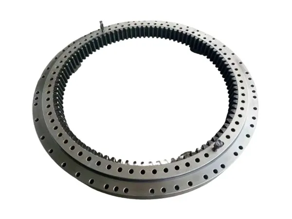
Slewing bearings are critical components in machinery that requires rotary motion, such as construction equipment, wind turbines, and industrial machinery. They are designed to support heavy loads and enable precise rotation, making them indispensable in various industries. This technical article delves into the engineering aspects, market trends, and applications of slewing bearings.

Engineering Aspects of Slewing Bearings

Slewing bearings

Slewing bearings are engineered to handle significant loads while maintaining rotational accuracy. They consist of an inner ring and an outer ring, with one usually incorporating a gear. The rings are designed with attachment holes for optimized power transmission and simple, quick connections between adjacent machine components. The bearing raceways, in conjunction with rolling elements and cages or spacers, are designed to accommodate loads acting singly or in combination, and in any direction.

Structural Optimization

The structural parameters of slewing bearings, such as ball diameter and the number of balls, are optimized for maximum carrying capacity and service life. Numerical methods based on static bearing capacity and fatigue life are used to optimize these parameters. Finite element models and local finite element models of the slewing bearing are established to analyze the carrying capacity of different structural parameters. The Hertz contact theory and experiments are used to compare the theoretically calculated load distribution, contact stress, contact area, and deformation.

Materials and Manufacturing

High-quality steel and advanced heat treatment processes are used in the manufacturing of slewing bearings. This provides a superior balance between hardness and toughness, enabling longer service life. The manufacturing processes are globally certified to ISO 14001 for environmental management, and OHSAS 18001 for health and safety management standards.

For more detailed information on slewing bearing applications, please visit: https://www.mcslewingbearings.com/en/a/news/slewing-bearings-applications.html