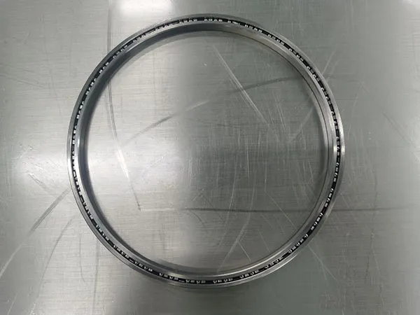
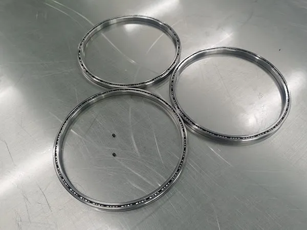
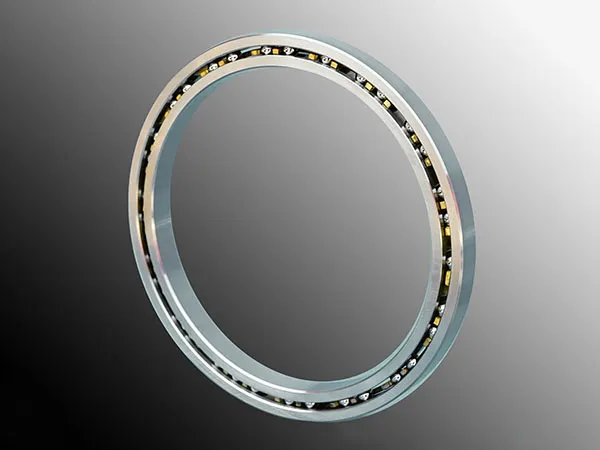
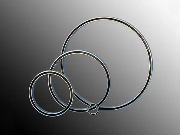
A slewing bearing is a specialized type of bearing that allows for rotational or slewing movement, typically used in heavy machinery. It consists of an inner ring and an outer ring, with rolling elements (like balls or rollers) between them. Unlike traditional bearings, slewing bearings are designed to handle both axial (up-and-down), radial (side-to-side), and moment (tilting) loads simultaneously.

Selecting a slewing bearing requires careful consideration of the application, load requirements, and environmental factors. Here’s a step-by-step guide to help you choose the right slewing bearing:

Slewing Bearing Selection

slewing bearing

1. Load Type and Magnitude

Radial Load: The force perpendicular to the axis of rotation.

Axial Load: The force parallel to the axis of rotation.

Moment Load: The force that causes the bearing to tilt or rotate about an axis.

Tip: Identify the magnitude of these loads and choose a bearing with appropriate load capacities. Most manufacturers provide load capacity charts for slewing bearings.

2. Operating Conditions

Speed: Consider the rotational speed and any speed variations.

Temperature: Check if the slewing bearing can withstand extreme temperature conditions.

Environment: Dust, moisture, and corrosive environments may require bearings with special seals or coatings.

3. Precision Requirements

Applications such as robotics or medical equipment require high-precision slewing bearings. For heavy machinery, moderate precision is usually sufficient.

4. Mounting and Installation

Ensure the bearing fits within the space available in the equipment.

Some bearings have internal or external gear teeth, while others are toothless—choose the right one depending on the drive system.

For more detailed information on slewing bearing selection, please click here: https://www.mcslewingbearings.com/en/a/news/slewing-bearing-selection.html

A slewing bearing (or slewing ring) is a type of large bearing designed to accommodate slow-turning or oscillating loads. These bearings are commonly used in applications where the bearing needs to support heavy loads while allowing for rotational or partial rotational movement. They are characterized by their ability to manage radial, axial, and tilting moments simultaneously.Installing a slewing bearing requires precision and careful handling to ensure its proper functioning.

Slewing Bearing Installation Guide

slewing bearing

1. Preparation:

Check the parts: Ensure all components, including the slewing bearing, bolts, and mounting structure, are clean and free of any damage or contamination.

Inspect the bearing: Look for signs of damage such as cracks, corrosion, or dirt. Clean the bearing if necessary.

Verify the flatness of the mounting surface: The mounting structure for the bearing should be flat, rigid, and free of distortions. Measure the flatness of the structure and compare it with the manufacturer’s specifications.

Prepare lifting tools: Due to the size and weight of slewing bearings, appropriate lifting equipment (e.g., a crane) should be prepared.

2. Mounting the Bearing:

Position the bearing: Use a crane or hoisting device to position the bearing on the mounting surface. Ensure that the bearing is handled carefully to avoid any impact or stress.

Align the bolt holes: Rotate the bearing carefully so that the bolt holes in the bearing match the bolt holes on the mounting structure.

Tighten bolts in stages: Insert all the bolts but do not tighten them fully at first. Tighten them in three stages to ensure uniform pressure:

First stage: Tighten bolts to 30-50% of the final torque value.

Second stage: Tighten bolts to 70-80% of the final torque.

Third stage: Tighten bolts to 100% of the specified torque value.

Cross-pattern tightening: Tighten the bolts in a criss-cross or star pattern to ensure even distribution of forces on the bearing.

slewing bearing

3. Lubrication:

Initial greasing: Most slewing bearings require lubrication before operation. Use the grease recommended by the manufacturer and fill the grease points (nipples) until fresh grease starts coming out from the seals.

Verify the seals: Check that the seals are intact and properly placed to prevent contamination.

4. Checking Clearance and Rotation:

Measure the backlash: Check the rotational clearance (backlash) of the bearing to ensure it meets the manufacturer’s specifications. Rotate the bearing to ensure smooth and consistent movement.

For more detailed information on slewing bearing installation, please click here: https://www.mcslewingbearings.com/en/a/news/slewing-bearing-installation.html

A flat glass tempering furnace is a specialized piece of equipment designed for the tempering of flat glass sheets, commonly used in architectural applications, automotive glass, and furniture. Here are the key aspects of a flat glass tempering furnace:

Key Features:

flat glass tempering furnace

Heating Zone:

Even Heating: Uses infrared heaters, convection heaters, or a combination to achieve uniform temperature across the glass surface.

Temperature Range: Typically heats glass to around 600°F to 1,200°F (315°C to 650°C).

Soaking Zone:

Controlled Environment: Maintains the glass at the target temperature for a specific time to ensure thorough heating.

Cooling Zone:

Rapid Quenching: Utilizes high-velocity air jets to cool the glass quickly, creating surface compression and enhancing strength.

Automation and Control:

Advanced Control Systems: Programmable logic controllers (PLCs) and touch screens for monitoring and adjusting temperature and timing.

Data Logging: Many furnaces include features for recording and analyzing the tempering process.

For more detailed information about the working principle of flat glass tempering furnace, please click to visit: https://www.shencglass.com/en/a/news/working-principle-of-flat-glass-tempering-furnace.html

The price of a glass tempering furnace can vary widely based on several factors, including the type, size, and specifications of the furnace, as well as the brand and additional features it may have. Here’s a breakdown of the factors affecting the price:

Factors Affecting the Price of a Glass Tempering Furnace:

glass tempering furnace

Type of Furnace:

Horizontal Tempering Furnace: More commonly used and typically more expensive due to its advanced technology and versatility in handling different glass sizes and thicknesses.

Vertical Tempering Furnace: Usually cheaper but less versatile and often used for smaller-scale operations or specific types of glass.

Size and Capacity:

The size and capacity of the furnace directly impact its cost. Larger furnaces capable of tempering bigger glass sheets or higher volumes will generally be more expensive.

Heating Method:

Furnaces with more advanced heating methods, like forced convection heating or radiation heating, may cost more due to increased energy efficiency and faster heating times.

Brand and Manufacturer:

Reputable brands with a track record of quality, reliability, and customer support often come with a premium price. However, they may offer better warranties and after-sales service.

Customization and Features:

Custom features such as automated loading/unloading systems, advanced control systems, specialized cooling systems, or energy-efficient components can increase the cost.

For more detailed information about glass tempering furnace prices, please click here: https://www.shencglass.com/en/a/news/tempering-furnace-price.html

The electricity consumption of a glass tempering furnace varies widely depending on several factors, such as the furnace size, type (horizontal or vertical), efficiency, the thickness and type of glass being processed, and production capacity. However, here are some general estimates:

Glass tempering furnace hourly power consumption

Small Glass Tempering Furnaces: These can consume anywhere from 50 to 200 kWh per hour.

Medium Glass Tempering Furnaces: These typically consume between 200 to 500 kWh per hour.

Large Industrial Glass Tempering Furnaces: These can consume upwards of 500 to 1000 kWh or more per hour, depending on their size and capacity.

Factors Affecting Electricity Consumption of a Glass Tempering Furnace

glass tempering furnace

Furnace Size and Type:

Small Furnaces: Usually consume between 50 to 200 kWh per hour.

Medium Furnaces: Typically consume between 200 to 500 kWh per hour.

Large Furnaces: Can consume 500 to 1000 kWh or more per hour.

Type of Furnace: Horizontal furnaces generally consume more electricity compared to vertical furnaces due to differences in heating mechanisms and loading processes.

Glass Thickness and Type:

Thicker glass requires more heating time and energy, leading to higher electricity consumption.

The type of glass (e.g., low-emissivity, laminated, or tinted glass) may also affect heating requirements.

Production Capacity and Batch Size:

Higher production capacities and larger batch sizes typically result in higher energy consumption due to increased heating and cooling requirements.

For more detailed information about the hourly power consumption of glass tempering furnaces, please click here: https://www.shencglass.com/en/a/news/glass-tempering-furnace-hourly-power-consumption.html

Linear vibrating screens are widely used in various industries for the separation and classification of materials. They operate on the principle of a linear motion, utilizing two vibrating motors that create a linear motion along the screen.

A circular vibrating screen is a type of screening equipment used to separate materials based on size.

The difference between linear vibrating screen and circular vibrating screen

Linear and circular vibrating screens are both used for sorting and separating materials, but they have different operational principles and applications.

Linear Vibrating Screen:

Movement: The screen moves in a straight line, creating a linear motion.

Design: Typically has a rectangular or square shape.

For more detailed information about the difference between circular vibrating screen and linear vibrating screen, please click to visit: https://www.zexciter.com/en/a/news/the-difference-between-linear-vibrating-screen-and-circular-vibrating-screen.html

Vibration motors are devices that generate mechanical vibrations for a variety of applications, such as haptic feedback in devices, industrial machinery, and consumer electronics. There are several types of vibration motors, each with distinct characteristics, designs, and applications.

Types of Vibration Motors

Vibration motors

Eccentric Rotating Mass (ERM) Motors

Description: ERM motors are DC motors with an unbalanced weight attached to the shaft. When the motor rotates, the centrifugal force generated by the offset weight causes the motor to vibrate.

Applications: Widely used in mobile phones, pagers, wearable devices, and other small handheld gadgets for haptic feedback.

Advantages: Simple design, cost-effective, easy to control the vibration intensity by varying the speed of rotation.

Disadvantages: The vibration is not uniform due to the rotating mass.

Linear Resonant Actuators (LRA):

Description: LRAs consist of a magnetic mass suspended by a spring, which oscillates when an AC signal is applied. They are tuned to resonate at a specific frequency, providing a strong vibration at a particular resonance.

Applications: Used in smartphones, tablets, gaming controllers, wearables, and other devices requiring precise haptic feedback.

Advantages: Faster response time, better energy efficiency, and more precise control over vibrations than ERM motors.

Disadvantages: More complex control circuitry is required, and they are typically more expensive than ERM motors.

Coin Vibration Motors:

Description: These are a type of ERM motor that is flat and coin-shaped. The eccentric mass is embedded in a circular housing, making it compact and easy to integrate into slim devices.

Applications: Commonly used in portable devices like smartphones, smartwatches, and fitness bands.

Advantages: Compact size, low power consumption, easy to mount.

Disadvantages: Limited vibration strength due to their small size.

Vibration motors

Brushless DC Vibration Motors:

Description: These motors use a brushless DC motor design, where the rotation of a magnet induces vibration without physical brushes. The vibration mechanism is similar to ERM but with higher efficiency and durability.

Applications: Industrial equipment, automotive applications, and more demanding environments requiring long life and reliability.

Advantages: Longer lifespan, lower maintenance, higher efficiency, and better control.

More detailed information about vibration motor types can be found at: https://www.zexciter.com/en/a/news/vibration-motors-types.html

Vibrating feeders are devices used to feed bulk materials continuously and uniformly to processing machines or conveyors. They are widely used in industries such as mining, metallurgy, coal, construction, chemical, and food processing. The specifications and models of vibrating feeders vary depending on the application, material to be handled, and desired capacity.

Specifications of Vibrating Feeders

Vibrating feeders

Capacity:

The capacity of vibrating feeders ranges from a few tons per hour (tph) to several hundred tph. Common capacities include 10, 50, 100, 200, and 500 tph, depending on the model and application.

Size of the Feeder Deck:

The width and length of the feeder deck can vary. Typical widths range from 300 mm to 3,000 mm, and lengths range from 600 mm to 6,000 mm.

Feeder Type:

Electromagnetic Vibrating Feeders: Ideal for smaller volumes and precise feeding applications.

Electromechanical Vibrating Feeders: Suitable for handling larger loads and for heavy-duty applications.

Grizzly Vibrating Feeders: These feeders have grizzly bars for separating fines and are used for handling materials with large lump sizes.

Vibration Frequency and Amplitude:

Frequency usually ranges from 750 to 3000 vibrations per minute.

Amplitude varies from 1 mm to 15 mm, depending on the material flow and feeder design.

Motor Power:

Motor power ranges from 0.5 kW to 15 kW or more, depending on the feeder size and capacity.

Material of Construction:

Made from various materials, such as carbon steel, stainless steel, and high-strength alloys, depending on the application and material to be handled.

Installation Type:

Available in stationary, mobile, or portable configurations depending on the setup and use.

For more detailed information on the specifications and models of vibrating feeders, please click here: https://www.zexciter.com/en/a/news/vibrating-feeder-specifications-and-models.html

A gantry welding machine is a type of welding equipment that uses a gantry structure to support and guide the welding head or torch along a workpiece. It is commonly used in automated welding processes for large, heavy, or complex structures, such as shipbuilding, bridge construction, steel fabrication, and large-scale industrial projects.Operating a gantry welding machine involves following a set of detailed procedures to ensure safe and efficient operation. Below is a general guide for operating a gantry welding machine.

Gantry Welding Machine Operating Procedures Guide

Gantry Welding Machine

1. Pre-Operation Inspection

Safety Gear: Ensure that you are wearing appropriate personal protective equipment (PPE), such as welding gloves, helmet with a proper filter lens, safety goggles, ear protection, and flame-resistant clothing.

Machine Condition: Inspect the welding machine for any visible damage or wear. Check for loose bolts, damaged cables, or any signs of leaks.

Check Electrical Connections: Ensure all electrical connections are secure, and there are no exposed wires.

Inspect Welding Consumables: Check the condition of the welding wire, electrodes, and flux. Replace or refill if necessary.

Test Gas Supply (if applicable): Ensure the shielding gas cylinder is properly connected, and the flow rate is set to the required level.

2. Machine Setup

Position the Gantry: Align the gantry in the desired position along the welding track or workpiece.

Secure the Workpiece: Properly clamp and secure the workpiece on the welding table or fixture to avoid movement during welding.

Adjust Welding Parameters: Set the welding current, voltage, speed, and other parameters according to the material type, thickness, and welding method (MIG, TIG, Submerged Arc Welding, etc.).

Set the Welding Torch: Position the welding torch or head at the correct distance and angle to the workpiece.

Gantry Welding Machine

3. Operation Start-Up

Power On the Machine: Turn on the main power supply and the welding machine.

Select Program or Mode: Choose the appropriate welding program or mode (manual, semi-automatic, or fully automatic) as per the job requirements.

For more detailed information about the gantry welding machine operation procedures, please click here: https://www.bota-weld.com/en/a/news/gantry-welding-machine-operation.html

An electricity power pole welding line is a specialized production line used for manufacturing electricity power poles, typically made from materials like steel or concrete.The process flow of an electricity power pole welding line typically involves several key steps.

Electricity power pole welding line process flow

electricity power pole welding line

1. Raw Material Preparation

Material Inspection: Check quality and specifications of incoming materials (steel or concrete).

Cutting: Use cutting machines to cut raw materials to required lengths for poles.

2. Component Fabrication

Forming: Shape the cut materials into the necessary profiles (for steel poles).

Drilling: Create holes for mounting brackets or other features as needed.

3. Welding

Assembly: Arrange the components in the correct configuration.

Welding: Use appropriate welding techniques (MIG, TIG, or submerged arc) to join the components securely.

electricity power pole welding line

4. Cooling and Stress Relief

Cooling: Allow welded sections to cool down naturally or use controlled cooling methods.

Stress Relief: Apply processes to relieve residual stresses if necessary.

5. Inspection and Quality Control

Visual Inspection: Check for visible defects in welds and overall structure.

Non-Destructive Testing (NDT): Perform tests like ultrasonic or radiographic inspection to assess weld integrity.

For more detailed information about the process flow of the power pole welding production line, please click to visit: https://www.bota-weld.com/en/a/news/electricity-power-pole-welding-line-process-flow.html