In modern welding automation, both welding column boom systems and welding robots play critical roles in improving efficiency, precision, and safety. While they may seem similar in purpose, these two systems are designed for different applications and operate using distinct principles. While both a welding column boom and a welding robot are automated tools used to improve welding processes, they differ significantly in their design, flexibility, and applications.
Difference Between A Welding Column Boom and A Welding Robot
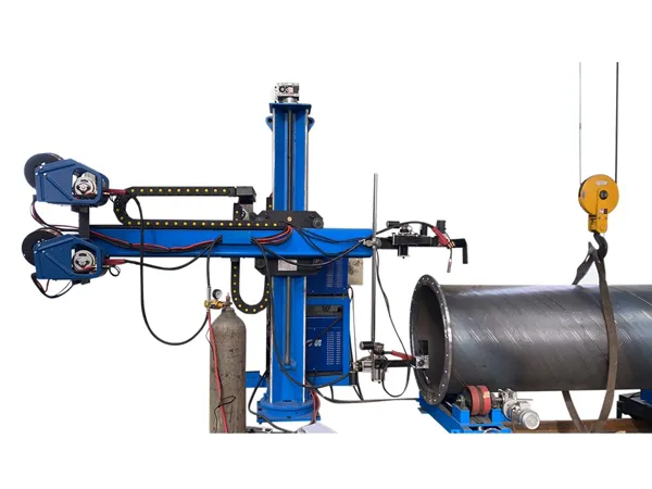
Welding Column Boom (Manipulator)
Design: A column boom system typically consists of a vertical column mounted on a stable base and a horizontal boom that extends from the column. The welding head is mounted on the end of the horizontal boom. The column allows for vertical movement, and the boom provides horizontal reach. Many also allow for 360-degree rotation of the column.
Movement & Control: Column booms offer precise linear and rotational movement. They are designed to move the welding torch along a pre-defined path, primarily for long, straight, or circumferential welds on large workpieces. While they can have advanced controls and often integrate with other automated equipment (like welding positioners or turning rolls), their motion is generally less complex and more constrained than a robot. They are manipulators that move the welding material to the workpiece, rather than moving the workpiece itself.
Flexibility: They are highly effective for repetitive, large-scale welding tasks on substantial components. However, they are less adaptable to complex, irregular geometries or tasks requiring multiple axes of motion beyond basic linear and rotational movement.
Applications: Commonly used in heavy equipment manufacturing, shipbuilding, pressure vessel fabrication, tank and pipe welding, and large-scale construction projects where long, consistent welds are required.
Advantages:
Excellent for long, continuous welds.
Can handle heavy welding heads and associated equipment (e.g., flux recovery systems for SAW).
Improves safety by removing welders from hazardous environments.
Enhances weld quality and consistency for their specific applications.
Can reduce welder fatigue.
Welding Robot
Design: A welding robot is typically a multi-axis articulated arm (similar to a human arm) that can move in numerous directions (typically 4, 6, or more axes). The welding torch is attached to the “wrist” of the robot.
Movement & Control: Robots are highly programmable and can perform complex, intricate movements. They use advanced controllers and software to execute precise welding paths, often guided by machine vision or touch sensing for adaptability. They can navigate around obstacles and weld in tight spaces.
…
For more detailed information about the difference between welding column boom and welding robot, please click here: https://www.bota-weld.com/en/a/news/difference-between-welding-column-boom-and-welding-robot.html