
One of the characteristics of the mold-molding mold is that hot steam and cooling water need to be introduced into the closed mold gas chamber to mature and cool the foam particles, which is different from the molding environment of molds such as plastic molds, metal molds and die-casting molds. The mold needs to form a foam pattern in a water state, which makes it difficult to use an automatic ejection mechanism for the lost mold, but the automatic ejection mechanism can obviously improve the molding efficiency and molding quality of the foam pattern, and reduce the foam pattern. The amount of deformation, and can reduce labor costs and labor intensity, especially for some of the large-sized flywheel shell, gearbox and internal cavity structure of the complex engine body of the lost foam casting, the effect is more obvious.
According to the molding process of the current foam pattern of the enterprise, it is possible to solve the automatic ejection of the foam pattern from two aspects: one is the molding equipment from the foam pattern-forming machine, and the other is the molding state from the foam pattern- Evaporative mold; for the molding machine, to realize the automatic ejection of the foam pattern, only the lower template of the molding machine, that is, the automatic ejection mechanism of the fixed template device, combined with the automatic ejection mechanism of other types of mold forming equipment, is available for selection. The hydraulic cylinder is ejected or the mechanical ejector is ejected. The biggest problem to be considered in the use of such a mechanism is to prevent leakage of hot steam during the molding of the foam pattern, whether it is a hydraulic cylinder or a mechanical top on the molding machine. Rod, leaking steam is a difficult problem to solve. The direct result of leaking steam will make the foam pattern not fully mature, the welding is not enough, affecting the strength of use and the quality of casting, and it is likely that oil will appear on the surface of the foam pattern. It is not easy to realize the automatic ejection of the foam according to the current molding machine; it has not been easy for many years. Development and practice, mold LFC lower mold plenum chamber is provided an automatic ejection mechanism is well achieved.
The automatic ejection mechanism of the cavity in the cavity of the lost mold is also unique. The gas chamber continuously experiences the alternating hot and cold cycles of hot steam and cooling water, thus requiring the parts of the automatic ejection mechanism to prevent rust and corrosion. Heat resistant, friction resistant, and non-deformable. According to the above requirements, the automatic ejector mechanism is the cylinder automatic ejector mechanism, and the spare parts included in the following figure have 7 accessories: 1. Aluminum alloy heat-resistant cylinder 2, copper gas pipe 3, stainless steel bolt 4, stainless steel connecting rod 5, copper guide sleeve 6, wrought aluminum ejector plate 7, copper ram.
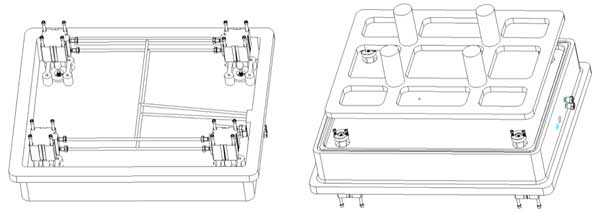
The positional relationship is: the inner cavity of the lower mold gas is closed around, the aluminum alloy heat-resistant cylinder 1 is located in the air chamber, and is fixed on the partition plate of the gas chamber through the stainless steel bolt 3, and the bottom plane of the heat-resistant cylinder is lower than the lower mold air chamber. The bottom plane, wherein the copper gas pipe 2 is connected to the gas source outside the gas chamber, the copper gas pipe 2 is provided with two sets with respect to the cylinder, one set of intake air, one set of exhaust gas; the piston of the heat resistant cylinder and the stainless steel connecting rod 4 Connected and screwed together, the other end of the stainless steel connecting rod 4 is connected through the copper guide sleeve 5 and the wrought aluminum ejector plate 6, and the connecting rod 4 and the ejector plate 6 are fastened by stainless steel bolts; The sleeve 5 is fixed on the partition plate of the lower mold air chamber by stainless steel bolts; the partition plate is in the middle of the ejector plate and the heat-resistant cylinder, and is formed integrally with the lower mold air chamber, and is cast together to ensure the use strength; the forged aluminum is ejected The plate is located on the parting surface of the lower mold air chamber, and sinks into the groove on the upper surface of the lower mold air chamber, the lower bottom surface is next to the air chamber partition plate, and the upper surface contacts the foam pattern, and is made in the groove of the lower mold air chamber. Reciprocating motion; copper is fixed on the forged aluminum ejector plate Rod 7, the jack 7 copper through a stainless steel bolt fastening the top plate on the top, with the ejector plate movement.
The working principle of the automatic ejection mechanism is divided into two processes: in the ejection process of the foam pattern, the air source switch fixed on the outdoor side of the lower mold gas is first twisted, so that the compressed air enters the bottom of the heat-resistant cylinder through the copper gas pipe, and the air pressure is adopted. The pressure causes the cylinder piston to move upwards, the piston transmits the upward moving force to the connecting rod, the connecting rod slowly moves upward through the copper guiding sleeve, and the ejector plate and the connecting rod are fastened together by the stainless steel bolt, and the connecting rod moves upward. In the process, the force can be transmitted to the ejector plate, and the ejector plate drives the foam pattern to move upwards. In order to ensure uniform force during the ejection process, the copper ejector and the ejector plate act together on the foam pattern. After the foam pattern is finished demoulding, it is the homing process of the automatic ejection mechanism, and the air source switch is twisted to the other side, so that the compressed air enters the top of the heat-resistant cylinder through the copper gas pipe. Under the action of air pressure, the cylinder piston completes the contraction movement, and then the ejector plate and the ejector rod are driven to return to the position through the connecting rod and the guide sleeve.
The following four principles should be noted for the use of the automatic ejection mechanism for the lost mold.
1. The assembly clearance of the ejector plate and the ejector pin is reasonable, and the movement is smooth during the demolding and homing process, and there is no stuck phenomenon;
2. The position of the cylinder and the ejector rod is designed reasonably to ensure that the foam pattern is evenly stressed, so that the foam pattern has no deformation phenomenon during the demoulding process;
3. The movement rhythm of the ejection cylinder is consistent, and the intake and exhaust are synchronously controllable;
4, the material of the ejector mechanism parts is selected to pay attention to oxidation and rust.
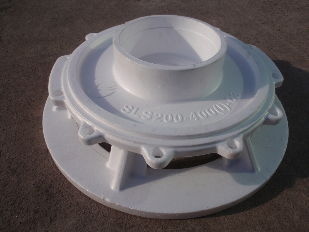
The following is an example to explain the positional requirements of the cylinders in the automatic ejection mechanism and the position design of the ejector, and an automatic ejection mechanism design of the large flywheel housing. This flywheel shell is shown below:
Its product dimensions: 972 * 964 * 206, the material is gray iron 200, foam material polystyrene, pre-foam foam material weight 22g / L; mold size: 1320 * 1290 * 420; analysis of the shape of the product cavity structure; The inner circumference of the inner cavity is reversed. It is necessary to design the inner side core insert of one week, and the external partial undercut. It is necessary to make the outer side core insert, which increases the difficulty of demoulding the foam pattern, and uses the air blow according to the ordinary demoulding. Or the method of spraying water, because of the influence of the self-weight of the side core insert, the white mold is difficult to take out, and the shape is too large, at least 2-3 foam forming operators are needed, and the mold is too large, the manual operation is inconvenient, and the foam pattern is easy. Deformation, in summary, the sub-mold needs to use an automatic ejection mechanism to assist in demolding.
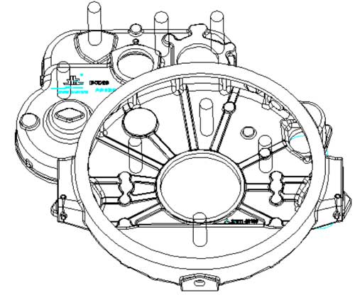
According to the analysis of the demoulding force of the foam pattern, the automatic ejection mechanism of the flywheel shell lost mold is shown in Figure 3: the ejector plate is arranged on the parting surface of the lower mold air chamber, and the outer shape of the ejector plate is 1170. *1140*150, the design of the ejector plate takes into account two aspects: First, the strength of the ejector plate, the gravity of the inner and outer wicking inserts of the flywheel shell acts on the ejector plate, and the ejector plate needs to be The mold release resistance of the foam pattern, the superposition of various forces, the strength of the ejector plate is sufficient, and the deformation is not bent during the demolding process, so the thinnest thickness of the stripper is not less than 25 mm, and the material is wrought aluminum; Secondly, considering the molding environment of the foam pattern, it is necessary to pass hot steam and cooling water. The ejector plate needs to reserve the through holes of the hot steam and the cooling water, and the through hole is designed to the bottom of the inner and outer core inserts, which is beneficial to the bottom. The hot steam and the cooling water enter the inner cavity of the side core insert for the mature cooling of the foam pattern.
8 sets of copper ejector pins are arranged on the ejector plate to assist the ejector plate to be demolded. The placement of the copper ejector pins should take into account the maximum and most deformable position of the foam pattern, according to the internal and external structure of the foam pattern and the side wicking inserts. Position analysis, four copper rams are arranged in the inner cavity of the flywheel housing, and the outer core peripheral side core insert is demoulded, and four copper ejector pins are arranged outside the flywheel shell to assist the flywheel shell outer side core insert Demoulding, the strength of the foam pattern is small, and the copper ram should be placed at a relatively thick wall thickness of the flywheel shell, and then the force area of the foam pattern should not be too small. The diameter of the copper ram used in this time is Φ40mm.
The flywheel housing has a large outer shape, and nine ejection cylinders are required in the inner cavity of the lower mold gas, and are arranged according to the force concentration point of the foam pattern, and 8 cores are arranged along the circumference according to the maximum shape of the ejection plate, and the center side core is drawn. There are more inserts, one more, and nine cylinders act on the ejector plate at the same time, which can meet the demoulding requirements of the foam shell of the flywheel shell.

