
R&D background:
As of 2017, China’s total installed capacity of electric motors has reached more than 400 million kW, and the annual power consumption has reached 1.2 trillion kWh, accounting for 60% of the country’s total electricity consumption, accounting for 80% of industrial electricity consumption, including fans, pumps and compressors. The total installed capacity has exceeded 200 million kW, and the annual power consumption has reached 800 billion kWh, accounting for about 40% of the country’s total electricity consumption. Therefore, the energy saving requirements on the motor are extremely great, and it is also the place where the energy saving effect can best be reflected.
As an important device for electromechanical energy conversion, the motor is the basic component of electric drive. It has a wide range of applications, many varieties of products and complicated specifications. Its product characteristics determine that the concentration of the industry is not high, and the production enterprises and the sub-sectors involved are more. Obvious periodic, regional, seasonal characteristics. As of 2018, the domestic production and supporting manufacturers of differential and medium-sized motors are more than 2,000, which has become an indispensable basic product in the national economy and national defense modernization. There are many manufacturers in the domestic differential and small and medium-sized motor industry. The market competition is mainly reflected in the technical content, price and production scale of the products. Due to the imperfect market mechanism, the price competition in the industry is fierce and has been a benign development of the industry. To adverse effects. With the enforcement of the motor energy efficiency label, the emergence of the market’s survival of the fittest and the further strengthening of the industry barriers, the price competition will gradually weaken. Foreign host manufacturers also purchase motor housings in large quantities in China, Siemens, ABB, Dongyuan, South Korea Hyosung and so on.
In this context, the invigorating motor casing production plant has sprung up on the land of China, and the various motorized areas in China’s motor market have been approved by the motor main engine factory. , Taizhou, Jingjiang, Wuxi, Jiamusi, Nanyang, etc., the construction of large and small lost foam production line thousand, Y series 80-400 model motor shell lost foam casting technology is mature and stable, lost foam process The casting process of the motor casing is fully embodied and the advantages are strong. First, the heat sink is straight and smooth, the spacing is the same, the appearance of the casting has no stitching line, smooth and smooth. Second, the casting precision reaches the CT8 standard, the roundness is high, and the machining allowance is small, as long as the white mold is not affected, the weight can be controlled. Third, the entire production process is small, the amount of castings is small, the corresponding labor cost of the production of castings is low, and the casting price has a large advantage. The commonality of the remaining lost foam casting advantages is the same for the lost flame casting of the motor casing, such as good casting environment, green and environmental protection, simplified process, high density of castings and so on.

Process requirements:
According to the above analysis, the six-point requirement for casting the motor casing using the lost foam process:
First, the direction of the heat sink is preferably horizontal and vertical, that is, the orientation of the heat sinks in four directions is uniform, although the radial heat sink can also open the mold, but the motor shell of this structure is recommended to be a manual mold. .
Second, the top thickness of the heat sink is guaranteed to be 3.2-5mm, and the height of the rounded fins reserved for R1.5-2mm is 30-60mm higher than the outer round surface.
Third, try to simplify the molding difficulty of the motor casing, and straighten the screw cover of the fixed end cover in four directions.
4. The grounding mark is placed in four orientations.
5. Optimize the inner core structure and try to avoid the possibility of undercutting.
6. The position and orientation of the junction box are as consistent as possible with the core pulling direction, simplifying the structure and avoiding bonding.
According to the casting process requirements of the motor casing, it is not difficult to find that the lost foam casting is more difficult.
First, the heat sink around the motor casing is thinner and taller, and the casting is prone to cold separation.
Second, the same roundness of the stator surface of the intermediate installation should be ensured to prevent deformation and excessive rounding.
Third, the motor shell casting generally adopts the top casting process, and the exhaust slag in the casting process is well treated. Based on the above analysis of the difficulty of the lost foam casting of the motor casing, the design points of the lost mold of the motor casing are mainly reflected in the classification, processing and insert material selection of the heat sink around the motor casing product. material.
Mold design:
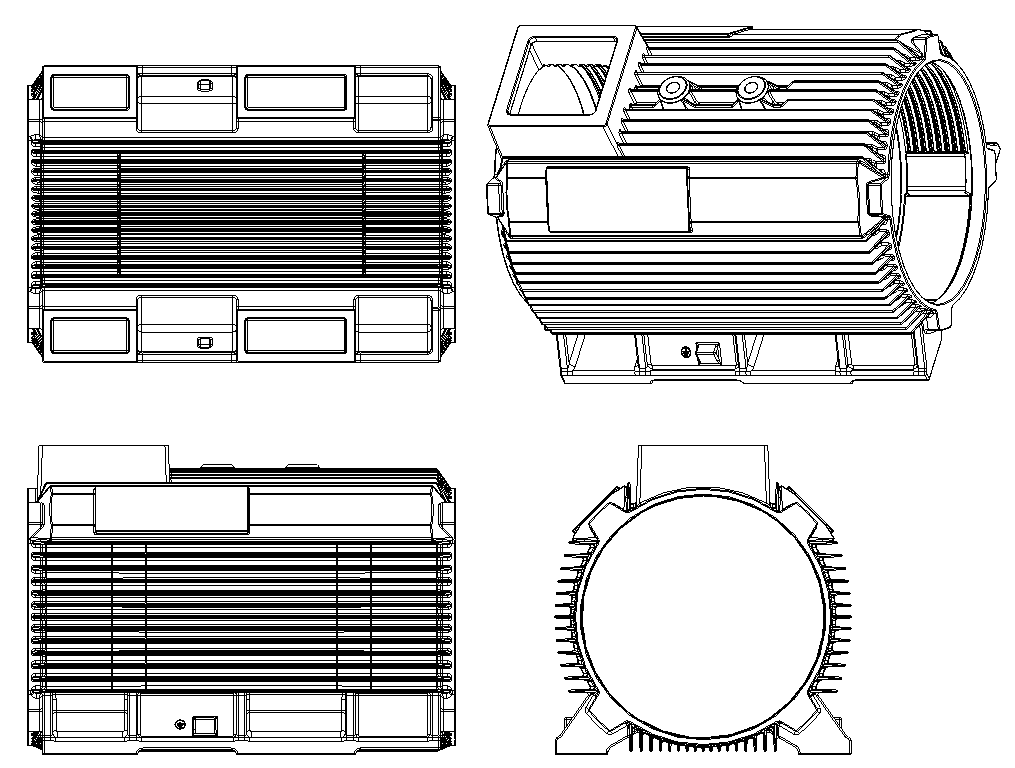
In order to solve the above problem of the lost foam casting process of the motor casing, it is necessary to design a lost foam mold for the motor casing, so that the white mold of the motor casing can meet three requirements:
First, the heat sink is fully formed, evenly matured, without gas traces, and without jagged.
Second, the motor shell white mold body looks beautiful, smooth, no granular or superheat caused by uneven heating.
Third, the molding operation is simple, the product consistency is good, the foam pattern has high precision, and the molding effect is good.
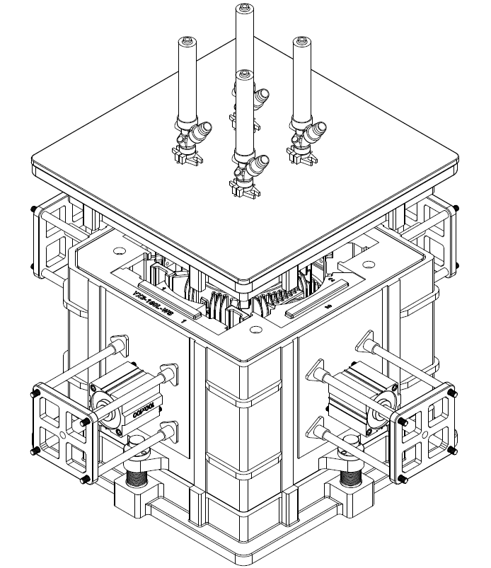
According to the mold assembly diagram:
Design a three-open mold motor shell lost mold, the mold mechanism includes automatic gun, upper mold, side core insert, core cylinder, lower mold, lower mold, upper core, upper mold sealing, positioning Plate and spring mechanism. The upper mold sealing plate is connected to the upper mold cavity of the upper end surface of the upper mold to form a sealing structure; the upper mold core is hollow and communicates with the inner cavity of the upper mold air chamber and the mold cavity; the lower mold includes a lower mold air chamber , the lower mold chamber 2 and the core; the lower mold chamber is a double-layer structure; the lower mold chamber 1 and the lower mold chamber are connected by a spring mechanism; the lower core is fixed to the lower mold chamber 2 and the upper core Symmetrically disposed; the inner cavity of the lower die chamber has four side core inserts uniformly distributed along the circumference for forming the heat sink around the motor casing; and the corresponding four side core inserts are respectively provided with core pull cylinders; The four core pulling cylinders are respectively fixed on the outer side of the lower mold one; the side core pulling inserts are respectively connected with the pistons of the corresponding core pulling cylinders through the guiding columns to form four side core pulling inserts. Under the action of four core-pulling cylinders, the inward movement is closed to form a mold cavity or an outwardly moving structure; the top of the upper mold sealing plate is fixed with an automatic material gun; the lower end of the automatic material gun passes through the inner cavity of the upper mold air chamber. The upper core is slidably connected to the upper mold chamber by bolts and springs; one end of the spring is connected with the upper mold core, and the other end is connected with the upper mold air chamber by bolts, and the lost mold is used in the automatic mold. When the gun is filled, the upper core and the lower core are closely adhered under the action of the spring force, and the upper mold chamber and the lower mold chamber are not in contact, thereby realizing the structure of double pre-opening.
The upper mold chamber has a positioning table around the chamber, and the lower mold chamber has a positioning groove that cooperates with the positioning table on the upper mold chamber; the positioning chamber and the lower mold chamber on the upper mold chamber The positioning grooves have a guiding mechanism for positioning and guiding the mold when the lost mold is closed.
The parting surface of the upper mold chamber has a reserved hole for the passage of hot steam and cooling water.
The outer side of the upper mold chamber, the lower template and the lower mold chamber, the lower template and the lower mold chamber, and the lower mold and the lower core contact surface each have a reserved hole through which hot steam and cooling water pass.
The three-opening structure of the motor casing is to make the lower die chamber closed without leaking and to achieve the effect of the limit side core insert. The three-opening structure of the motor casing is composed of an upper die, a lower die 1 and a lower die 2. The lower die 1 and the lower die 2 are combined by a spring mechanism to form a lower die chamber. The finite-position bosses at the two ends of the four side core inserts are inserted into the upper die limit groove and the lower die limit groove respectively in the mold clamping state, and the side draw is prevented. The core insert is retracted. When filling, the upper mold is lifted by 20mm, then the lower mold spring mechanism bounces the lower mold. The lower side of the 12mm insert is separated from the lower mold. At this time, the 20mm pre-opening of the filling is performed, which will make the motor shell foam-like. The heat sink is full and flawless. When the mold is opened, the upper mold is lifted, and the upper mold limit groove is separated from the four side core inserts, the spring structure springs up the lower mold, and the core cylinder structure causes the four links to drive the side core insert to retreat. When the motor shell foam is taken out, the side of the motor shell is formed. The three-opening structure of the motor casing is composed of an upper die, a lower die 1, a lower die 2 and a spring mechanism. The spring structure is composed of a lower die, a lower limit hole, a lower die second limit hole, a guide post and a spring. The spring structure realizes the first opening of the lower mold 1 and the lower mold 2. The molding machine drives the upper mold to move upward to make the upper mold and the lower mold a second mold opening, two mold opening, and a three-layer mold structure. The mold, the lower mold, and the lower mold 2) are combined into a three-open mold structure of the motor casing, which realizes the perfect molding of the motor shell foam.
The new structure of the three-opening mold of the motor shell lost mold. The automatic feeding is realized by the automatic gun, which ensures that the heat sink of the motor shell foam pattern is full and has no defects; the side core pulling insert and the core pulling cylinder realize the automatic core pulling, the set hot steam through hole and the cooling water. The through hole realizes automatic heating and cooling, greatly improves the forming efficiency of the white mold, reduces the labor intensity and production cost of the worker, ensures the consistency of the white mold forming, has simple molding operation, good product consistency, high precision of the foam pattern, Good molding effect.
Detailed ways:
The working process of the three-opening structure of the motor casing is:
The first step is to hoist the motor shell mold between the four guide columns of the vertical molding machine, and fix the upper mold air chamber to the upper template (ie moving template) of the molding machine through the pressing plate, and press the lower mold air chamber through the pressing plate. Fixed on the lower die plate of the vertical forming machine (ie, the fixed die plate), turn on the vent pipe and the feed pipe of the automatic gun, turn on the vent pipe of the positioning cylinder and the core cylinder, and open the upper die chamber and the lower die. a hot steam pipe and a cooling water pipe of the air chamber;
Step 2: Debug the mold, adjust the opening and closing stroke of the vertical molding machine to the stroke suitable for the mold to open and take out the foam, and then press the mold tightly by the vertical molding machine to ensure smooth opening and closing of the mold without any stuck phenomenon; Material time, hot steam pressure, cooling time;
The third step: in the filling stage, when the mold is charged by the automatic gun, the upper mold chamber drives the upper core into the mold cavity after the side core insert is closed. At this time, between the upper mold and the lower mold Leave a gap of 6-8mm, and the upper core and the lower core are closely attached under the action of the spring force, which is equivalent to the mold cavity is 6-8mm larger, it is easier to fill the mold cavity, making use of The automatic gun fills the pre-expanded foam particles into the mold cavity by the negative pressure method, that is, the pre-opening feeding is realized, and after the feeding is finished, the upper mold and the lower mold are completely closed, in the process, the heat sink is partially The unfilled part is filled with the unfilled part when the vertical molding machine drives the upper mold downward to ensure that the foam particles are completely filled into the mold cavity, thereby ensuring the formation of the foam pattern heat sink; Pass hot steam, keep pressure, until the foam material is fully expanded, matured, blended, formed, turn off the steam valve, pass the cooling water, cool, set, open the drain valve, drain the cooling water, open the upper and lower molds first, complete Separation of core and motor shell foam The positioning cylinder drives the positioning plate to move downward, and moves the positioning boss to the lower side of the side core insert, and the core pulling cylinder drives the side core insert to disengage the heat sink of the motor shell foam and the side core insert, completing The release of the heat sink, the upper and lower molds are opened to the mold adjustment stroke, and the foam pattern is taken out from the lower mold to complete the mold opening action; when the mold is closed, the side core insert is closed first by the core cylinder, and the upper and lower molds are closed again. The positioning cylinder of the lower mold drives the positioning plate to complete the positioning limit of the opposite side core insert, ends the mold clamping, refills, and completes a molding process.
Note: The above mold structure Luoyang Liushi Mould Co., Ltd. has applied for a patent, counterfeiting will be investigated!
Invention patent number:
ZL 2012 1 0303995.X
ZL 2016 1 0057821.8
ZL 2016 1 0216915.5
Utility model patent number:
ZL 2012 2 0423206.1
ZL 2012 2 0423548.3
ZL 2012 2 0423999.7
ZL 2012 2 0423475.8
ZL 2016 2 0084122.8

