Labor costs consistently represent the single largest controllable expense in tunnel construction projects. For decades, traditional formwork methods have required extensive manual handling, skilled carpenters on-site, and prolonged assembly cycles that drive up both direct wages and project timelines. The introduction of automated tunnel formwork systems has fundamentally shifted this equation. Industry data from multiple large-scale infrastructure projects indicates that switching to an automated system can reduce on-site labor requirements by approximately 40%. This article examines the engineering mechanisms behind that reduction, the operational implications for contractors, and what the investment looks like for a typical mid-size tunnel project, drawing on case experience from Gaofei’s deployment across Asia and the Middle East.

The Core Mechanism of Automation in Tunnel Formwork

Automated tunnel formwork differs from conventional systems primarily in how it handles the three critical phases: positioning, pouring, and striking. Traditional systems rely on a crew of 8-12 workers to manually align steel panels, install tie rods, adjust braces, and later dismantle everything piece by piece. An automated system integrates hydraulic cylinders, electromechanical drives, and a central control unit that moves the formwork as a single rigid assembly.

Hydraulic Self-Stripping and Traveling

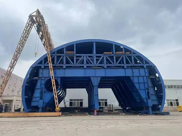
In a Gaofei automated tunnel formwork system, the entire formwork arch is mounted on a traveling carriage. After the concrete has cured, the hydraulic system retracts the panels by a pre-set distance – typically 50-80 mm – without any manual intervention. The carriage then moves forward along rails to the next pour position. This single sequence eliminates the need for a separate dismantling crew, crane lifting of panels, and re-assembly. On a typical 300-meter tunnel section, this reduces the number of workers per shift from 12 to 7.

Integrated Concrete Delivery and Vibration

Automated systems often include built-in concrete distribution arms and remote-controlled vibrators. Workers no longer need to manually drag hoses or handle immersion vibrators at height. Instead, one operator controls both the concrete flow and vibration pattern from a safe position, further reducing the crew size and eliminating a common source of safety risk.

Why 40% Labor Reduction Is Realistic
The 40% figure is not an arbitrary benchmark. It emerges from a combination of three measurable factors:

  • Reduced crew size per cycle: Automated striking and traveling cut the number of workers needed for formwork handling by 50-60%.
  • Compressed cycle time: A typical 10-meter pour cycle in conventional formwork takes 24-36 hours (including stripping, cleaning, oiling, re-positioning). Automated systems can reduce this to 12-18 hours, meaning fewer total labor hours per linear meter of tunnel.
  • Lower rework and adjustment: Hydraulic precision ensures consistent alignment, reducing the need for skilled carpenters to correct geometry. Unskilled workers can handle most tasks after brief training.

Data from Gaofei’s project on the Delhi Metro extension showed that the labor input dropped from 1.8 man-hours per cubic meter of concrete to 1.1 man-hours – a 39% reduction, matching the headline figure closely.

…

Click here for more details on how automated tunnel formwork can reduce labor costs by 40%: https://www.gf-bridge-tunnel.com/a/blog/automated-tunnel-labor.html
Selecting the right bearing for a thin-section application is a critical engineering decision that directly impacts performance, service life, and cost. Two of the most common options are thin section ball bearings and cross-roller bearings. Though they occupy the same radial space envelope, their mechanical characteristics differ substantially. Understanding these differences is essential for engineers and procurement specialists who need to match the bearing to the actual load and motion requirements of the system. This article provides a structured comparison, outlining the strengths and limitations of each type, and offers practical guidance for making an informed selection.

The Fundamentals: Thin Section Ball Bearings vs. Cross-Roller Bearings

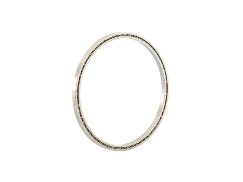
Thin-section bearings are designed to save weight and space while maintaining high rotational accuracy. They are widely used in robotics, medical equipment, radar systems, and semiconductor manufacturing. The two dominant designs are the ball-type and the roller-type, distinguished by their rolling elements and contact geometry.

Thin Section Ball Bearings

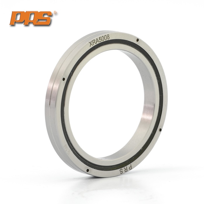
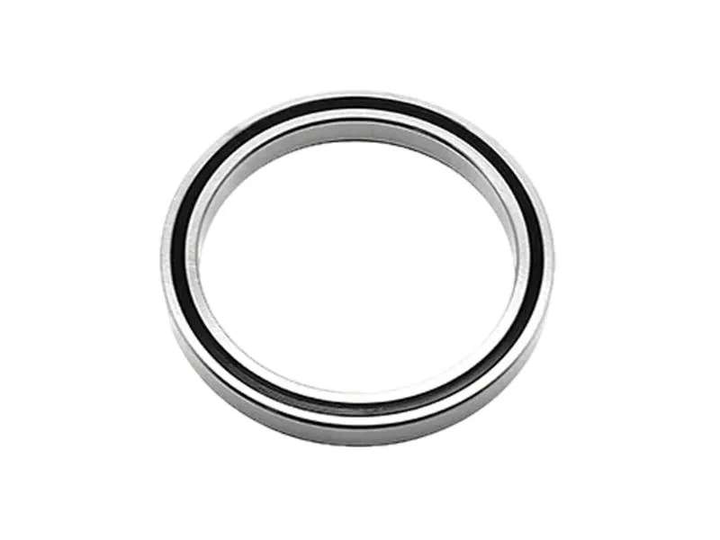
Thin section ball bearings use hardened steel balls as rolling elements. They typically have a deep or angular contact raceway, allowing them to handle radial, axial, and moment loads with relatively low friction. Because the contact area between a ball and the raceway is a point, the bearing can achieve high rotational speeds with minimal heat generation. They are available in various cross-section series such as A (angular contact), C (deep groove), and X (four-point contact), each optimizing a specific load distribution.

Cross-Roller Bearings

Cross-roller bearings contain cylindrical rollers arranged perpendicularly in alternating directions. This configuration provides line contact between rollers and raceways, significantly increasing the load-carrying capacity compared to balls of the same cross-sectional size. The crossing arrangement enables the bearing to support radial, axial, and moment loads simultaneously with high rigidity. Cross-roller bearings are often the preferred choice for applications demanding exceptional stiffness and load capacity in a compact envelope.

…

For more detailed information comparing thin-section ball bearings and crossed roller bearings, please click here: https://www.prsbearings.com/news/bearing-comparison-guide/

Every gram of mass removed from an unmanned aerial vehicle (UAV) directly contributes to longer mission endurance, higher usable payload, or greater flight agility. Yet in the search for lighter structural components, engineers frequently overlook a hidden heavyweight: the bearing assembly. For years, aerospace designers accepted the mass penalty of conventional bearings as unavoidable. That paradigm is shifting, largely because of precision thin section bearings, which offer a remarkable balance of reduced cross-section, low weight, and high load-carrying robustness. These compact rolling elements are enabling next-generation rotorcraft, gimbal systems, and surveillance turrets to shed structural weight without sacrificing the rigidity needed for stable flight performance. For design teams evaluating bearing options, understanding the mechanical and operational advantages of thin section technology is essential to making an informed specification decision.

Why UAV Engineering Demands a New Class of Bearings

The structural requirements of a UAV flight control system are unforgiving. Unlike ground-based machines that can tolerate heavier actuation components, a UAV must allocate its takeoff mass with precision. Each bearing in the gimbal, actuator linkage, or propeller pitch control mechanism affects the mass of the supporting bracket, the motor sizing, and ultimately the battery capacity. A heavier bearing therefore cascades into a heavier aircraft at multiple levels of the system architecture.

Conventional bearings, designed decades ago, maintain cross-sections that are often oversized for modern UAV applications. They are built for heavy-duty industrial shafts with standardized load-carrying conventions, offering far higher load ratings than a small aerial platform will ever encounter. The result is an unnecessary weight and space penalty inside precision mechanisms where every millimeter of envelope matters.

What Exactly Are Thin Section Bearings?

A thin section bearing is defined by its cross-sectional geometry, not by its bore diameter. Where a standard ball bearing has a cross-section that scales proportionally with the bore, a thin section bearing maintains a small, reduced cross-section across a wide range of bore sizes. This allows engineers to use a large-diameter bearing for moment stability and drift resistance without carrying the associated bulk and mass of a traditional bearing.

…

Click here for more details on lightweight yet robust thin-section bearings for drones: https://www.prsbearings.com/news/uav-bearing-guide/

A thin section ball bearing is a precision component that challenges every rule of conventional bearing lubrication. Its compact cross-section saves space and weight, but it also limits the amount of lubricant that can be retained inside the bearing. Without a disciplined lubrication strategy, even the best-engineered bearing will fail prematurely. This guide is written for engineers and maintenance professionals who want to extend the service life of thin section ball bearings through proven lubrication practices. From selecting the correct grease or oil to establishing realistic re-lubrication intervals, each step matters. Later, we explain how PRS supports customers with bearing specification and lubrication expertise.

Why Lubrication Determines Thin Section Bearing Life

In conventional bearings, a generous grease fill can mask lubrication errors. Thin section ball bearings do not offer that luxury. The balls and raceways are proportionally smaller, the ring cross-section is slender, and the available cavity for lubricant is limited. Every microliter of lubrication has to work harder.

The Role of the Elastohydrodynamic Film

Under normal operating conditions, a rolling element bearing creates an elastohydrodynamic lubricant film that separates the rolling elements from the raceways. In a thin section bearing, the contact geometry produces very high localized stresses. If the film is too thin, metal-to-metal contact occurs, causing wear, micro-spalling, and premature flaking. The film thickness must be protected by choosing a lubricant with the correct base oil viscosity at the operating temperature and by ensuring enough lubricant is delivered to the raceway regularly.

Common Failure Modes Linked to Lubrication

  • Raceway wear caused by insufficient film separation.
  • Micro-pitting and surface fatigue due to moisture contamination or thin oil film.
  • Smearing or scuffing during low-speed oscillating motion with marginal lubrication.
  • Corrosion of raceways and balls when the lubricant lacks rust inhibitors or has broken down.
  • Premature grease hardening or bleeding that permits dry running.

Any one of these failure modes can reduce the life of a thin section bearing from its rated life to a fraction of it. That is why lubrication cannot be an afterthought.

…

Click here for more detailed information on lubrication techniques to extend the service life of thin-section ball bearings: https://www.prsbearings.com/news/lubrication-tips/

When rotating equipment must perform reliably in washdown, marine, chemical, or pharmaceutical environments, standard bearing steel quickly becomes a liability. Corrosion leads to pitting, lubricant degradation, and premature failure. Stainless steel thin section bearings offer a proven solution, combining a compact cross-section with the inherent corrosion resistance of martensitic or austenitic stainless steels. This article provides a technical yet practical overview for engineers and procurement specialists seeking to specify the right bearing for demanding corrosive applications.

Why Thin Section Bearings Are Critical in Corrosive Environments

Thin section bearings are characterized by a relatively small radial cross-section compared to their bore diameter. This design saves weight, reduces housing space, and allows for larger shafts or smaller overall machine envelopes. In corrosive environments, the stakes are higher. A bearing failure in a food processing line or offshore actuator can halt production and create safety hazards. Stainless steel thin section bearings maintain the same dimensional advantages while resisting rust and chemical attack.

Material Selection: Not All Stainless Steel Is Equal

The phrase “stainless” is an umbrella term. For thin section bearings, the most common materials are AISI 440C, AISI 304, and precipitation-hardening grades like 17-4 PH. The choice dictates hardness, corrosion resistance, and load capacity.

  • 440C is a high-carbon martensitic stainless steel that can be hardened to approximately 58–60 HRC. It offers good corrosion resistance in mild environments and is suitable for higher load capacities.
  • 304 is an austenitic stainless steel with excellent corrosion resistance but low hardness. It is used for bearing rings in low-load, high-corrosion applications where hardness is secondary.
  • 17-4 PH combines good corrosion resistance with high strength and hardness after precipitation hardening, making it a preferred choice for marine and chemical processing.

For rolling elements, 440C or ceramic (silicon nitride) balls are common. Hybrid bearings with stainless rings and ceramic balls offer both corrosion resistance and electrical insulation, which is an added advantage in motor applications.

…

Click here for more details on thin-section stainless steel bearings designed for corrosive environments: https://www.prsbearings.com/news/thin-section-bearings-1/

Precision optical instruments—from gimbaled cameras and laser trackers to spectrometers and telescope mounts—depend on extremely accurate rotary motion. The bearings that support these systems must minimize runout, friction, and size while maintaining repeatable positioning under varied thermal and load conditions. Thin section bearings have emerged as the preferred solution for such demanding applications, offering a unique balance of compact geometry and high precision. This article examines why these bearings are essential for precision optical instruments, how they contribute to system performance, and what engineers should consider when selecting a supplier.

Why Thin Section Bearings Are Critical for Optical Instrument Performance

Optical instruments require precise angular alignment between optical elements, sensors, and targets. Any radial or axial displacement of a rotating component can cause beam deviation, image blur, or measurement error. Standard bearings often have large cross-sections that add unnecessary weight and envelope, which is problematic for portable or space-constrained instruments. Thin section bearings maintain a small cross-section relative to their bore diameter, allowing larger hollow shafts for cabling, optics, or scanning mechanisms without sacrificing stiffness or accuracy.

Furthermore, thin section bearings offer design flexibility. Their reduced radial height means instrument designers can place rotary stages closer to the optical axis, minimizing Abbe errors and improving overall system accuracy. In multi-axis gimbals, the compact bearing envelope enables tighter package densities and reduced inertia, which directly benefits servo control bandwidth and settling time.

Key Performance Advantages of Thin Section Bearings

When selecting bearings for precision optical instruments, several performance characteristics become decisive. Thin section bearings, especially those engineered by specialists like PRS, deliver measurable advantages over conventional bearing types.

  • High rotational accuracy: Ultra-low radial and axial runout, often in the sub-micrometer range, ensures consistent optical alignment.
  • Low and uniform friction torque: Smooth, predictable motion is critical for fine positioning and closed-loop control.
  • Compact cross-section: Saves space and weight, enabling miniaturization and easier integration into optical subassemblies.
  • High stiffness-to-weight ratio: Maintains structural rigidity without adding mass that could induce vibration or thermal drift.
  • Wide operating temperature range: Stable geometry and material choices accommodate thermal expansion differences in optical housings.
  • Interchangeable configurations: Available in radial, angular contact, and four-point contact designs to suit varying axial and moment loads.

Radial vs. Angular Contact Thin Section Bearings

Radial thin section bearings handle primarily radial loads and offer low friction, making them suitable for simple turntables. Angular contact thin section bearings, on the other hand, provide higher axial and moment stiffness, which is essential for gimbals and scanners that experience overturning moments. Four-point contact versions combine high load capacity with a single bearing race, reducing component count and optimizing axial space.

…

For more detailed information on thin-section bearings for precision optical instruments, please click here: https://www.prsbearings.com/news/thin-section-bearings/

Selecting the right crucible for high-temperature melting applications directly impacts operational costs, product quality, and equipment longevity. While both graphite and silicon carbide crucibles are widely used in foundries and laboratories, their cost-effectiveness differs significantly based on melting temperature, thermal cycling frequency, and the type of metals processed. This article provides an objective cost-effectiveness comparison between graphite crucibles and silicon carbide crucibles, drawing on industry data and practical field experience. We will also highlight how Cangzhou Carbon has engineered crucible solutions that optimize the balance between upfront investment and long-term savings.

1. Material Properties and Performance Profiles

Thermal Conductivity and Heat Transfer Efficiency

Graphite crucibles naturally excel in thermal conductivity, typically ranging from 80 to 130 W/m·K, which allows rapid heat penetration and uniform temperature distribution. This characteristic reduces energy consumption and shortens melting cycles, especially for aluminum, copper alloys, and precious metals. In contrast, silicon carbide crucibles offer lower thermal conductivity (about 30–50 W/m·K) but provide superior thermal shock resistance. For applications requiring frequent heating and cooling, such as induction melting, the durability of silicon carbide can offset its slower heat-up time.

Maximum Operating Temperature and Oxidation Resistance

Standard graphite begins to oxidize in air above 400°C, though high-purity or coated grades can withstand up to 3000°C in inert atmospheres. Silicon carbide crucibles maintain structural integrity up to 1600°C in oxidizing environments, making them suitable for steel and iron melting where open flame or electric resistance furnaces create oxidizing conditions. However, graphite’s ability to operate in vacuum or reducing atmospheres gives it a distinct advantage for specialized metallurgy.

2. Lifecycle Cost Analysis: Graphite vs Silicon Carbide

To truly compare cost-effectiveness, we must evaluate total cost of ownership (TCO), which includes purchase price, service life, maintenance, and energy impact. Below is a structured comparison based on typical industrial data:

  • Initial Purchase Cost: Standard graphite crucibles are 20–30% less expensive than silicon carbide equivalents. However, high-density large graphite crucibles can be cost-comparable when specifications demand extreme purity.
  • Service Life in Aluminum Melting: Graphite crucibles typically last 2–4 months with daily use, while silicon carbide crucibles can extend to 6–12 months, depending on flux usage and dross removal practices.
  • Energy Efficiency Impact: Graphite’s higher thermal conductivity reduces melt time by 15–20%, lowering energy bills. Over a year of continuous operation, the savings can outweigh the replacement cost of an additional graphite crucible.
  • Maintenance and Downtime: Silicon carbide crucibles require less frequent replacement, reducing furnace downtime. However, graphite crucibles from manufacturers like Cangzhou Carbon are designed with uniform density to minimize hot spots and extend life through proper handling.

Real-World TCO Example: Melting Brass (1200°C)

Consider a mid-sized foundry melting 500 kg of brass per shift, 5 days a week. Using a graphite crucible (cost 40% less, replaced every 4 months) versus a silicon carbide crucible (replaced every 8 months) results in a net TCO difference of about 12% in favor of graphite, thanks to reduced energy consumption and lower replacement frequency of the graphite crucible when properly maintained. However, if the same foundry melts iron at 1500°C or uses a gas-fired furnace with high oxygen exposure, the silicon carbide crucible becomes the more cost-effective choice due to longer life and reduced oxidation failures.

…

For more detailed information comparing the cost-effectiveness of graphite crucibles and silicon carbide crucibles, please click here: https://www.czgraphite.com/a/news/crucible-comparison.html

In the world of high-temperature metallurgy, vacuum melting presents unique challenges that demand specialized tooling. Among these, the graphite crucible stands as a critical component, directly influencing melt quality, process efficiency, and operational safety. Engineers and procurement specialists seeking a graphite crucible for vacuum melting must evaluate purity, thermal stability, mechanical strength, and service life. This article examines the key features that define a reliable crucible for vacuum environments, with a focus on how Cangzhou Carbon delivers solutions tailored to these stringent requirements.

The Role of the Graphite Crucible in Vacuum Melting

Vacuum melting is used for producing high-purity alloys, superalloys, and reactive metals such as titanium and zirconium. The crucible must withstand extreme temperatures (up to 2000°C or higher), rapid thermal cycling, and aggressive chemical interactions with molten metals. Unlike conventional melting in air, vacuum conditions eliminate oxidation but introduce risks of outgassing, contamination from crucible materials, and structural failure. Therefore, a graphite crucible for vacuum melting must possess specific properties that go beyond those of standard graphite crucibles.

High Density and Low Porosity

A crucible used in vacuum must have minimal open porosity. Open pores can trap gases and moisture, which are released under vacuum and high temperature, causing contamination or bubbling in the melt. High-density graphite (typically >1.85 g/cm³) reduces gas permeability and improves mechanical strength. Cangzhou Carbon manufactures crucibles using isostatic pressing and fine-grain graphite to achieve density above 1.90 g/cm³, ensuring excellent vacuum-tightness.

Exceptional Thermal Shock Resistance

Vacuum melting often involves rapid heating and cooling cycles. The crucible must resist cracking caused by thermal gradients. Fine-grain graphite with optimized binder systems provides higher thermal conductivity and lower coefficient of thermal expansion, enabling the crucible to endure repeated quenching. Our crucibles are engineered with a thermal shock resistance index that exceeds industry norms, reducing downtime and replacement costs.

High Purity to Prevent Melt Contamination

Any impurities in the crucible—such as sulfur, boron, or metallic elements—can leach into the molten metal and alter its properties. For vacuum melting, crucibles require ultra-high purity (ash content <50 ppm, often <20 ppm). Cangzhou Carbon utilizes high-purity raw materials and a dedicated purification process (graphitization at >2400°C) to minimize ash and volatile residues. This ensures that the crucible does not become a source of contamination even in sensitive applications like semiconductor grade silicon or superalloys.

Mechanical and Chemical Stability Under Vacuum

During vacuum melting, the crucible experiences not only thermal stress but also chemical attack from molten metals and slags. The graphite material must resist erosion and wetting by aggressive melts. Key features include:

  • Low wettability: High-precision surface finishing reduces metal penetration and sticking.
  • Excellent corrosion resistance: The carbon lattice resists attack from many molten metals (e.g., copper, aluminum, nickel alloys) when properly graphitized.
  • High compressive strength: At elevated temperatures, graphite actually increases in strength (up to 2500°C). Crucibles must maintain structural integrity during handling and thermal cycling.

Our crucibles are designed with a uniform fine-grain microstructure that minimizes anisotropic effects, providing consistent mechanical performance in all directions.

…

For more details on the key features of graphite crucibles for vacuum melting, please click here: https://www.czgraphite.com/a/news/crucible-vacuum-features.html

Graphite crucibles are indispensable in high-temperature applications such as metal melting, alloy casting, and laboratory analysis. However, when exposed to extreme heat in the presence of oxygen, graphite begins to oxidize — a process that gradually erodes the crucible wall, reduces its structural integrity, and shortens its service life. For industries that rely on consistent thermal performance and cost-efficiency, preventing oxidation is not just a maintenance issue; it is a strategic priority. This article presents a comprehensive, technically grounded approach to mitigating graphite crucible oxidation at high temperatures, covering material selection, protective coatings, operational best practices, and the tailored solutions offered by Cangzhou Carbon.

Understanding the Oxidation Mechanism

Graphite oxidizes when carbon atoms react with oxygen at elevated temperatures, typically above 500°C (932°F). The reaction produces carbon monoxide or carbon dioxide gas, which escapes from the surface, leaving behind a porous and weakened structure. The rate of oxidation accelerates exponentially with temperature. In practical terms, a crucible subjected to repeated cycles above 1200°C without protection can lose 3–5% of its mass per hour, drastically reducing its lifespan and increasing the risk of catastrophic failure during a melt.

Factors That Accelerate Oxidation

  • Temperature: Every 100°C rise above 600°C roughly doubles the oxidation rate.
  • Oxygen availability: Open-air furnaces expose crucibles to constant airflow; even a small leak in an inert atmosphere can trigger oxidation.
  • Fluctuating thermal cycles: Rapid heating and cooling create micro-cracks that allow oxygen to penetrate deeper.
  • Impurities in the graphite: Certain contaminants (e.g., iron oxides) catalyze oxidation.

Recognizing these factors is the first step toward selecting effective prevention strategies.

Choose the Right Graphite Grade and Density

Not all graphite crucibles are created equal. The base material’s density, purity, and grain structure directly influence oxidation resistance. Higher-density graphite has fewer internal pores, which reduces the surface area available for oxygen attack. Fine-grained, isostatically pressed graphite typically exhibits superior oxidation resistance compared to coarse-grained, vibration-molded alternatives.

Key Specifications to Look For

  • Bulk density: ≥ 1.85 g/cm³ is recommended for high-heat applications.
  • Ash content: < 0.3% to minimize catalytic impurities.
  • Oxidation threshold: Some premium grades are formulated to resist oxidation up to 900°C in air without coating.

When purchasing crucibles, always review the manufacturer’s data sheet for oxidation start temperature and maximum safe operating temperature in air. Cangzhou Carbon offers a range of high-density, ultra-pure graphite materials specifically engineered for demanding thermal environments.

Apply Protective Surface Coatings

Coatings are the most widely adopted method for preventing graphite crucible oxidation. They function as a physical barrier that separates the graphite from oxygen, while also reflecting some radiant heat. The ideal coating must withstand the same temperatures as the crucible, adhere well under thermal cycling, and not contaminate the melt.

…

Click here for more detailed information on how to prevent graphite crucibles from oxidizing at high temperatures: https://www.czgraphite.com/a/news/prevent-graphite-oxidation.html

For foundries and smelting operations working with non-ferrous metals such as aluminum, copper, zinc, and their alloys, the choice of crucible directly impacts melt quality, energy consumption, and overall productivity. While standard crucibles serve general purposes, the demanding conditions of non-ferrous metal casting often require customized solutions. Custom graphite crucibles are engineered to match specific furnace geometries, temperature profiles, and alloy chemistries, delivering longer service life and consistent performance. Cangzhou Carbon, a trusted manufacturer in the crucible industry, specializes in designing and producing custom graphite crucibles that meet the exact needs of each casting operation, ensuring maximum efficiency and cost-effectiveness.

1. Why Customization Matters in Non-Ferrous Metal Casting

Non-ferrous metals present unique challenges during melting and holding. Aluminum alloys can be highly aggressive to refractory materials, while copper and brass require high operating temperatures that accelerate thermal fatigue. Off-the-shelf crucibles may not provide the best fit for these variables, leading to premature failure or suboptimal heat transfer. Customization allows you to optimize three critical aspects: dimensions, material composition, and wall thickness.

Tailored Dimensions for Specific Furnace Types

Crucibles must fit precisely within induction furnaces, gas-fired furnaces, or resistance furnaces to maintain proper metal flow and heat distribution. Cangzhou Carbon works with clients to define exact outer and inner diameters, height, and lip design, ensuring seamless integration. A poorly fitting crucible can cause uneven heating, increase energy waste, and create safety hazards from metal spillage.

Optimized Material Composition for Temperature and Corrosion Resistance

Different non-ferrous metals require different levels of oxidation resistance and chemical stability. Custom formulations can adjust the ratio of graphite, silicon carbide, clay, and other additives. For example, crucibles used for melting zinc or aluminum need excellent resistance to molten metal attack, while those for copper require higher thermal conductivity and strength at temperatures above 1100°C. Cangzhou Carbon uses proprietary recipes to tailor these properties without compromising cost.

Cost Efficiency and Extended Service Life

A custom crucible may have a higher upfront price, but its extended lifespan and reduced downtime quickly offset the initial investment. By matching the crucible’s thermal expansion characteristics to your furnace’s heating cycle, you minimize cracking and deformation. This results in fewer crucible changes, lower refractory costs, and more consistent production schedules.

2. Key Performance Indicators for Custom Graphite Crucibles

When evaluating custom crucible options, focus on these critical performance metrics that directly affect your casting operation:

  • Oxidation resistance – The ability to withstand repeated heating in an oxidizing atmosphere without excessive weight loss or surface deterioration.
  • Thermal conductivity – Higher conductivity means faster melting and lower energy consumption; custom formulas can balance conductivity with mechanical strength.
  • Mechanical strength – Especially important for large crucibles or those used in tilt-pour applications; should resist cracks from thermal shock and physical handling.
  • Thermal shock resistance – Critical for batch melting where crucibles are rapidly heated and cooled; improved by controlling grain size and additives.
  • Corrosion resistance – Resistance to alloying elements like copper, iron, and silicon that can dissolve graphite; enhanced through surface treatments or denser microstructures.

Click here for more details on custom graphite crucibles for non-ferrous metal casting: https://www.czgraphite.com/a/news/custom-graphite-crucibles.html