Rodamientos de rodillos cruzados tipo delgado se han convertido en una solución preferida en industrias que exigen alta precisión, diseño compacto, y rendimiento de carga confiable. Ingenieros que trabajan con robótica., sistemas de automatización, dispositivos médicos, y los equipos CNC a menudo seleccionan estos rodamientos porque ofrecen una rigidez excepcional y al mismo tiempo mantienen un perfil delgado.. Sin embargo, Muchos usuarios todavía tienen dificultades para comprender completamente cómo funciona la capacidad de carga en estos rodamientos especializados y cómo seleccionar el modelo adecuado para su aplicación..
Esta guía explica de forma clara la capacidad de carga de los rodamientos de rodillos cruzados de tipo delgado., práctico, y basado en la experiencia. Se centra en consideraciones reales de ingeniería en lugar de definiciones de libros de texto., ayudarle a tomar decisiones informadas que mejoren el rendimiento y la vida útil del equipo.
¿Qué son los rodamientos de rodillos cruzados de tipo delgado??
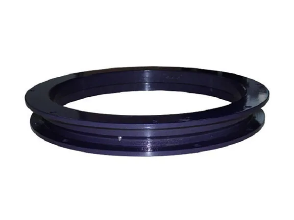
Los rodamientos de rodillos cruzados de tipo delgado son una variación de los rodamientos de rodillos cruzados diseñados con una sección transversal reducida.. Los fabricantes disponen los rodillos cilíndricos de forma ortogonal. (a 90 grados) entre los anillos interior y exterior. Esta estructura permite que un solo rodamiento maneje simultáneamente cargas radiales., cargas axiales, y cargas de momento.
A diferencia de los rodamientos tradicionales que requieren múltiples unidades para soportar diferentes direcciones de carga, Los rodamientos de rodillos cruzados de tipo delgado simplifican el diseño del sistema.. Su estructura compacta los hace ideales para aplicaciones donde las limitaciones de espacio y peso son críticas..

Capacidad de carga de los rodamientos de rodillos cruzados de tipo delgado
La capacidad de carga no es un valor fijo único. Los ingenieros suelen evaluarlo a través de dos parámetros principales.:
Capacidad de carga dinámica (do): Este valor representa la carga que un rodamiento puede soportar durante la rotación durante una vida útil definida..
Capacidad de carga estática (C₀): Este valor indica la carga máxima que un rodamiento puede soportar sin deformación permanente cuando está estacionario..
Los rodamientos de rodillos cruzados de tipo delgado suelen mostrar una alta capacidad de carga en relación con su tamaño.. Sin embargo, El rendimiento real depende en gran medida de las condiciones de funcionamiento., precisión de instalación, y distribución de carga.
Factores clave que afectan la capacidad de carga
1. Geometría de rodamientos y disposición de rodillos
La disposición cruzada de los rodillos garantiza que la carga se distribuya uniformemente en múltiples puntos de contacto.. Este diseño aumenta significativamente la rigidez y la capacidad de carga en comparación con los rodamientos de bolas estándar..
Diseños tipo delgado, sin embargo, reducir el espesor del material. Los ingenieros deben equilibrar la compacidad con la fuerza. Una estructura de anillo más delgada puede reducir ligeramente la capacidad de carga absoluta., pero la geometría interna optimizada compensa esto en la mayoría de las aplicaciones..
2. Calidad del material y tratamiento térmico
El acero para rodamientos de alta calidad y los procesos de tratamiento térmico precisos influyen directamente en la capacidad de carga. Fabricantes que controlan la dureza., tensión residual, y la microestructura puede mejorar significativamente la resistencia a la fatiga.
En aplicaciones del mundo real, Los rodamientos fabricados con materiales inferiores a menudo fallan prematuramente., incluso si sus índices de carga de catálogo parecen similares. Esta es la razón por la que abastecerse de fabricantes confiables es fundamental para el rendimiento a largo plazo..
…
Para obtener más información sobre cómo calcular la capacidad de carga de rodamientos de rodillos cruzados delgados y qué factores afectan la capacidad de carga, por favor haga clic para visitar: https://www.prsbearings.com/a/news/load-capacity-of-slim-type-crossed-roller-bearings.html