For any engineer working with rotating machinery—whether in construction equipment, wind turbines, or industrial robotics—understanding slewing bearing load capacity is not just a technical detail; it is the foundation of reliable design. Selecting the wrong bearing or misjudging the applied loads can lead to premature failure, costly downtime, or even catastrophic structural failure. This article breaks down the three fundamental load components, the factors that influence capacity, and a practical selection framework. We will also highlight how LYMC, a trusted manufacturer of high-precision slewing bearings, engineers its products to meet demanding load requirements with proven performance.

Understanding the Three Types of Load on a Slewing Bearing

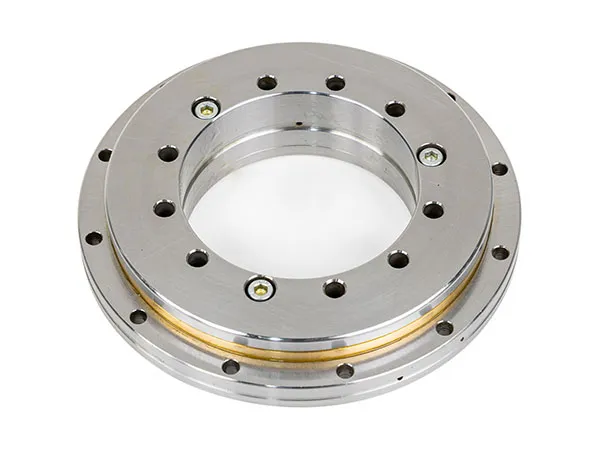
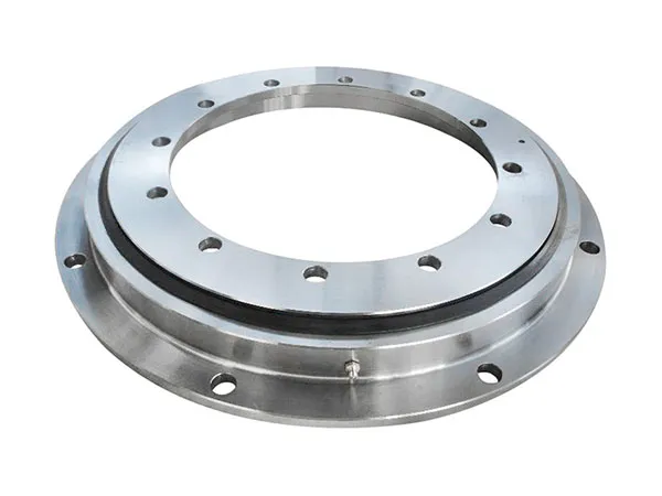
A slewing bearing must simultaneously support axial loads, radial loads, and tilting moments. Each type imposes different stress distributions on the raceways and rolling elements, and real-world applications rarely see pure loading—most involve combinations of all three.

Axial Load (Thrust Load)

Axial load acts parallel to the bearing’s axis of rotation. In a crane, for example, the weight of the boom and lifted load produces a downward axial force. Slewing bearings are generally strongest in the axial direction, but the magnitude and direction (upward vs. downward) must be considered. LYMC designs raceway profiles to maximize axial load distribution, reducing contact stress at the edge of the rollers.

Radial Load

Radial load acts perpendicular to the rotation axis. In horizontal applications such as indexing tables or excavator swing systems, radial forces from side loads or gear reactions can be significant. While slewing bearings are not optimized for pure radial loads, modern designs with crossed roller elements or four-point contact balls provide moderate radial capacity. Engineers must verify that the radial component does not exceed the bearing’s rating.

Tilting Moment (Moment Load)

The tilting moment is often the most critical load type for slewing bearings. It results from offset axial loads or lateral forces that create a torque about the bearing’s center. For example, a tower crane’s jib creates a large overturning moment that the slewing bearing must resist. Capacity against tilting moment is typically limited by raceway indentation and fatigue life. LYMC’s proprietary heat treatment and raceway grinding processes improve moment capacity by up to 15% compared to standard industry benchmarks.

Key Factors That Influence Load Capacity

Load capacity is not a fixed number; it depends on material properties, geometry, lubrication, and operating conditions. Understanding these factors helps engineers avoid over-specification (waste) or under-specification (risk).

For more information on the load-bearing capacity of slewing bearings that every engineer should know, please click here:https://www.mcslewingbearings.com/a/news/slewing-load-capacity.html

A crane is only as reliable as its slewing bearing. This critical component enables 360-degree rotation while supporting immense axial, radial, and tilting loads. Neglecting its maintenance can lead to catastrophic failures, costly downtime, and significantly shortened equipment life. However, with a structured maintenance regime, operators can dramatically extend crane lifespan and reduce total cost of ownership. This article outlines the essential practices for slewing bearing care, drawing on industry best practices and the specialized expertise of LYMC in heavy-duty rotating solutions.

The Critical Role of the Slewing Bearing in Crane Longevity

The slewing bearing acts as the mechanical pivot point between the crane’s upper structure and its undercarriage or foundation. It must withstand extreme forces while maintaining smooth, precise rotation. Over time, wear accumulates from friction, contamination, and micro-movements. Even minor degradation in the bearing’s raceways or rolling elements can amplify vibrations, increase drive motor loads, and accelerate fatigue in surrounding structures. Proper slewing bearing maintenance is therefore not optional—it is a direct determinant of the crane’s service life. Operators who treat the bearing as a consumable item without proactive care often face premature replacement costs that dwarf the investment in regular upkeep.

Common Causes of Slewing Bearing Failure

Understanding failure modes helps prioritize maintenance actions. The most frequent culprits include:

  • Inadequate lubrication: Insufficient grease or wrong type leads to metal-to-metal contact and rapid wear.
  • Contamination: Dirt, water, and abrasive particles enter through damaged seals, causing three-body abrasion.
  • Uneven loading: Repeated off-center loads or exceeding rated capacity induces local overstress and brinelling.
  • Corrosion: Moisture trapped in the bearing raceway initiates pitting and flaking.
  • Bolt loosening: Loss of preload in mounting bolts allows relative motion, fretting, and structural misalignment.

Each of these issues can be mitigated through systematic inspection and corrective action before irreversible damage occurs.

For more information on proper slewing bearing maintenance to maximize crane lifespan, please click here:https://www.mcslewingbearings.com/a/news/bearing-maintenance-.html

Slewing bearings are critical components in heavy machinery, from cranes and excavators to wind turbines and marine equipment. When they begin to fail, the consequences can be catastrophic: unplanned downtime, secondary damage, and even safety hazards. Recognizing the early warning signs of a failing slewing bearing can save your operation thousands of dollars in repairs and lost production. In this article, we outline the top five indicators that your slewing bearing needs immediate replacement — and what to do next to keep your equipment running safely.

1. Unusual Noise and Vibration During Operation

One of the most common early signs of slewing bearing degradation is abnormal noise or vibration. A healthy bearing operates with a smooth, consistent hum. If you hear grinding, clicking, or intermittent scraping sounds, it often indicates internal raceway damage, spalling, or contamination. Vibration that increases with load or rotation speed is equally concerning.

What Causes These Sounds?

  • Fatigue spalling on raceways or rolling elements
  • Brinelling from shock loads or improper mounting
  • Foreign debris entering the bearing cavity
  • Loss of lubrication film leading to metal-to-metal contact

Ignoring these auditory and tactile clues allows damage to propagate rapidly. Any sustained change in noise or vibration warrants immediate inspection. If the bearing is already showing visible wear, replacement with a high-quality unit from LYMC is the only reliable solution.

2. Excessive Clearance or Backlash

Slewing bearings are designed with precise internal clearance to accommodate thermal expansion and load deflection. Over time, wear on the raceways and rolling elements increases this clearance, resulting in backlash — a noticeable play between the turntable and the base structure. In excavators and cranes, this manifests as a delayed or loose response when the upper structure rotates.

For more information on the five signs that a slewing bearing needs immediate replacement, please click here:https://www.mcslewingbearings.com/a/news/slewing-bearing-signs.html

When selecting the right bearing for your rotating machinery, the choice often comes down to a slewing bearing versus a traditional bearing. Both serve the fundamental purpose of enabling rotational motion while supporting loads, yet their design philosophies, application scopes, and performance characteristics differ significantly. Understanding these differences is critical for engineers and procurement professionals who need to optimize equipment reliability, cost efficiency, and operational longevity. This article provides a rigorous, side-by-side comparison to help you determine which bearing type best suits your specific requirements. We will also highlight insights from LYMC, a manufacturer with extensive experience in both domains.

1. Fundamental Design and Structure Differences

The most apparent distinction between slewing bearings and traditional bearings lies in their physical architecture and how they handle forces. Traditional bearings—such as ball, roller, or tapered roller bearings—are typically compact, standardized components designed for high-speed rotation with moderate radial and axial loads. In contrast, slewing bearings (also known as slewing rings) are large-diameter, integrated assemblies that can simultaneously sustain heavy axial loads, radial loads, and tilting moments.

Load Capacity and Direction

Slewing bearings excel in applications where the load is not purely radial or axial but involves combined forces and overturning moments. Their design often incorporates multiple raceways with rows of balls or rollers (e.g., four-point contact ball or crossed roller) to capture forces from multiple directions. Traditional bearings, on the other hand, are optimized for uni‑directional or bi‑directional loading (e.g., deep‑groove ball bearings for radial loads, thrust bearings for axial loads). When tilting moments are present, traditional bearings may require complex mounting arrangements or multiple bearings in a back‑to‑back configuration, increasing system complexity.

Installation Complexity

Traditional bearings are generally off‑the‑shelf components that can be mounted using standard shaft and housing fits. Installation is relatively straightforward, often requiring only press‑fitting or heat‑fit methods. Slewing bearings, however, are bolted directly to adjacent structures (e.g., a turntable and a base) using a ring of mounting holes. This demands precise alignment and torque control, but it eliminates the need for additional housings or shafts. LYMC’s application engineers note that while slewing bearing installation is more involved, it simplifies the overall system design in heavy‑duty rotary applications such as cranes, excavators, and wind turbines.

2. Performance and Application Comparison

The following list summarizes key performance criteria where slewing bearings and traditional bearings diverge:

  • Speed capability: Traditional bearings operate at high RPM (thousands of revolutions per minute). Slewing bearings are designed for slow to moderate rotation (typically under 100 RPM).

For more detailed information on the main differences between slewing bearings and traditional bearings, please click to visit:https://www.mcslewingbearings.com/a/news/slewing-bearing-vs-traditional-bearing.html

For aggregate producers, achieving a consistent 1-inch minus product from a jaw crusher can be the difference between a profitable shift and costly rework. The 1-inch minus fraction—material that passes through a 1-inch square screen—is a critical specification for road base, concrete aggregates, and many construction applications. However, inconsistency in crusher output leads to increased recirculating loads, higher wear costs, and off-spec material that requires additional processing. The key lies in understanding and precisely adjusting a few critical crusher settings. In this guide, we draw on YUDE’s decade of experience in crushing solutions to walk you through the exact adjustments needed to produce a uniform 1-inch minus product, shift after shift.

Understanding 1-Inch Minus: Why Consistency Matters

One-inch minus material typically refers to aggregate that passes a 1-inch screen, often with a maximum top size of 1 inch and a fines content that can vary depending on the application. For road base, a consistent gradation ensures proper compaction and load-bearing strength. For concrete, it affects workability and strength uniformity. When your jaw crusher produces a mix where some rocks are oversize (plus 1 inch) and others are too fine, you face two problems: (1) you must screen out the oversize and recrush it, increasing circulating load; (2) excessive fines can lead to binder issues in asphalt or concrete. Consistent 1-inch minus means not only hitting the top size but also maintaining a stable particle shape and distribution.

Critical Jaw Crusher Settings for Consistent 1-Inch Minus

Achieving consistent output from a jaw crusher depends on three primary adjustable parameters: closed-side setting (CSS), crusher speed (RPM), and feed characteristics. Each interacts with the others, so systematic adjustment is essential.

More information on achieving consistent sub-1-inch crushing accuracy through these jaw crusher setups can be found by clicking here:https://www.yd-crusher.com/a/news/jaw-crusher-settings.html

For quarry operators, the relentless pursuit of higher production volumes often hits a bottleneck at the primary crushing stage. Inefficient equipment not only slows throughput but also escalates operating costs through increased downtime and energy consumption. YUDE introduces its latest high-capacity jaw crusher, engineered specifically to break these constraints. By combining advanced crushing chamber geometry with heavy-duty construction, this machine delivers a substantial boost in output while maintaining material quality. The following analysis details how YUDE’s innovation addresses the core challenges of modern quarry operations, offering a reliable path to higher profitability.

Understanding the Need for High-Capacity Crushing in Modern Quarries

Quarries today face mounting pressure to produce more aggregate with tighter margins. The primary crusher sets the pace for the entire plant. A low-capacity jaw crusher forces downstream equipment to operate below optimum levels, creating a ripple effect of inefficiency. YUDE recognizes that simply increasing motor power is not enough; the design must optimize feed-opening dimensions, toggle angle, and stroke length to maximize material throughput while minimizing wear. High-capacity crushing directly translates to fewer passes, reduced recirculating loads, and lower fuel consumption per ton. Moreover, as regulatory standards tighten, operators need machines that can handle varying feed sizes and hardness without compromising output consistency. YUDE’s solution addresses these realities with a focused engineering approach.

Design Philosophy Behind YUDE High-Capacity Jaw Crusher

The core design revolves around a deeper, wider crushing chamber combined with a steep toggle plate angle. This configuration allows material to be crushed more efficiently, reducing the tendency for packing and increasing the reduction ratio. The high throw motion accelerates the crushing cycle, enabling the machine to process larger feed sizes at higher capacities. Every structural component, from the pitman to the flywheels, is stress-analyzed to ensure longevity under peak loads.

Key Features of YUDE High-Capacity Jaw Crusher

YUDE has integrated several proprietary technologies that differentiate its crusher from conventional designs. The following features contribute directly to higher output and operational uptime:

  • Optimized Crushing Chamber Geometry – A curved jaw die profile that reduces material slippage and increases throughput by up to 15% over standard straight chambers, according to internal field tests.

For more information about this high-capacity jaw crusher that can increase your quarry’s output, please click here:https://www.yd-crusher.com/a/news/high-capacity-jaw-cr.html

In the demanding world of aggregate production and mining, the jaw crusher is the workhorse of primary crushing. Yet, its relentless operation often brings costly maintenance challenges—from frequent liner replacements to unscheduled downtime. Understanding the features that directly cut these expenses is critical for operators aiming to maximize profitability. This article examines five engineering characteristics that demonstrably lower jaw crusher maintenance costs, with practical insights drawn from YUDE’s decades of crusher manufacturing experience.

1. Robust Frame and Pitman Design: Eliminating Structural Fatigue

Maintenance costs often spike when the crusher frame or pitman develops cracks or misalignment. A substandard weldment or insufficiently reinforced structure accelerates wear on bearings and jaw dies, requiring expensive repairs.

YUDE’s Approach: Finite Element Analysis Optimization

YUDE engineers use finite element analysis (FEA) to identify stress concentration points and reinforce them with precise rib placements. The result is a rigid, heat-treated frame that maintains alignment under peak crushing loads. This structural stability reduces bearing stress and extends the intervals between rebuilds.

  • High-strength forged eccentric shaft – Minimizes deflection and fatigue, reducing the risk of shaft breakage.
  • Reinforced pitman assembly – Distributing load evenly across the frame cuts down on localized wear.

By investing in a robust, well-engineered base, operators can expect fewer emergency interventions and lower long-term maintenance budgets.

2. Advanced Jaw Die Profile and Materials: Prolonging Liner Life

Jaw dies are the most frequently replaced wear parts. Traditional straight-profile dies often lead to uneven wear, forcing early replacement and increasing material costs.

For more information on 5 key features for reducing jaw crusher maintenance costs, please click here:https://www.yd-crusher.com/a/news/reduce-the-maintenance-cost-of-jaw-crushers.html

Selecting the right crusher for primary crushing is a critical decision that directly impacts downstream efficiency, capital expenditure, and operational costs. While cone crushers are widely used in secondary and tertiary stages, many operators overlook the fundamental advantages of jaw crushers in the primary role. This article provides a professional, data-driven comparison to explain why jaw crushers consistently outperform cone crushers for primary crushing applications, and how YUDE engineering solutions maximize these benefits.

1. Fundamental Design Differences Suited for Primary Duty

The primary crusher must handle the largest, hardest, and most irregularly shaped feed material directly from the mine or quarry. Jaw crushers employ a straightforward compression mechanism: a fixed jaw and a moving jaw create a wedge-shaped chamber. This design excels at accepting oversized rocks without bridging or blockage.

Why Jaw Crushers Handle Oversize Better

A jaw crusher’s feed opening is rectangular and significantly wider than a cone crusher’s bowl. For example, a typical 30×48 jaw crusher can accept boulders up to 700 mm, while a cone crusher of similar horsepower requires prescreening or grizzly feeder to avoid jamming. Jaw crushers have a higher tolerance for non-uniform feed—blasted rock with sharp edges, elongated slabs, and clay content can pass through, whereas a cone crusher’s annular chamber would clog or cause excessive wear.

  • Cone crusher limitation: Requires choke feeding and even distribution to maintain stable operation.
  • Jaw crusher advantage: Capable of intermittent, surge feeding common in primary circuits.

2. Superior Throughput for Coarse Reduction Ratios

Primary crushing demands a reduction ratio of 4:1 to 6:1. Jaw crushers naturally achieve this in a single pass. Cone crushers, designed for finer reduction (6:1 to 8:1), often require a larger closed side setting (CSS) to avoid overload, resulting in lower throughput and higher recirculating loads.

For more information about jaw crushers being superior to cone crushers in primary crushing, please click to visit:https://www.yd-crusher.com/a/news/jaw-vs-cone-primary.html

When engineers face the challenge of achieving maximum rigidity within a confined axial space, traditional bearing solutions often fall short. Crossed roller bearings offer a compelling answer—combining the load-carrying capacity of roller bearings with a remarkably thin cross-section. Unlike ball bearings or conventional crossed roller designs, the unique roller arrangement in these bearings provides high stiffness in multiple directions while reducing overall installation height. For applications where every millimeter matters—such as robotics, medical imaging, and machine tool rotary tables—this technology has become indispensable. In this article, we explore the mechanical principles, performance advantages, and practical considerations when specifying Crossed Roller Bearings, with a focus on PRS solutions that have gained recognition in demanding industrial environments.

Understanding the Structure and Working Principle

A crossed roller bearing consists of cylindrical rollers arranged in alternating perpendicular directions (0° and 90°) between two raceways. This orthogonal arrangement allows the bearing to support radial, axial, and moment loads simultaneously with minimal clearance. The rollers are separated by a cage or spacer to prevent metal-to-metal contact, reducing friction and wear.

Why Crossed Arrangement Improves Rigidity

In a standard roller bearing, all rollers are parallel, limiting the direction of load support. By crossing the rollers at 90°, the bearing can resist forces from multiple axes without requiring additional bearings. This design inherently provides higher stiffness because the contact area between each roller and the raceway is a line (rather than a point in ball bearings), distributing the load over a larger surface. The result is a bearing that can handle significant tilting moments while maintaining extremely low rotational resistance.

Thin Package: The Cross-Sectional Advantage

The term “thin package” refers to the bearing’s minimal radial and axial cross-section relative to its diameter. Crossed roller bearings are typically produced with a rectangular or square cross-section that is small compared to the bore diameter—often in the range of 5 mm to 20 mm wide for bearings up to 1 meter in diameter. This compactness is achieved by eliminating the need for separate thrust and radial bearings. Engineers can integrate the bearing into a narrow annular space, reducing overall system weight and size.

Key Performance Benefits Over Alternative Bearing Types

When deciding between crossed roller bearings, ball bearings, and other roller variants, several performance metrics favor the crossed roller design:

  • High Rigidity Under Combined Loads: The orthogonal rollers create a stiff ‘X’ structure that resists both axial and radial forces. Unlike ball bearings, which only offer point contact, the line contact of crossed rollers reduces elastic deformation under load. This is critical for precision positioning in CNC machines and inspection equipment.

For more information on the slim, lightweight, and high-rigidity design of crossed roller bearings, please click here:https://www.prsbearings.com/a/news/crossed-roller-beari.html

Rotary tables are the backbone of precision machining, assembly, and inspection equipment. When a rotary table deflects under load, it introduces angular errors that compromise part accuracy, repeatability, and surface finish. Engineers often struggle to balance stiffness, compactness, and load capacity. Crossed roller bearings have emerged as a proven mechanical solution to mitigate deflection without sacrificing space or weight. This article examines the root causes of rotary table deflection, explains how the unique geometry of crossed roller bearings counteracts these forces, and provides practical guidance for incorporating them into your design. For over a decade, PRS has specialized in precision crossed roller bearing solutions, and the principles discussed here reflect industry-proven practices.

Understanding Rotary Table Deflection: Causes and Consequences

Rotary table deflection occurs when external forces—axial, radial, or moment loads—cause the table to tilt or shift from its ideal axis of rotation. In machining centers, this deflection typically arises from cutting forces; in measurement equipment, it results from workpiece weight or inertial forces during indexing. The primary mechanical contributors are:

  • Bearing clearance: Even minimal play in conventional ball bearings allows the table to rock under moment loads.
  • Limited stiffness: Single-row ball or roller bearings have lower radial and moment stiffness compared to crossed configurations.
  • Elastic deformation: Under heavy combined loads, the bearing raceways and rolling elements deform, leading to micro-deflections.

The consequences are significant: increased part rejection, shortened tool life, and reduced machine uptime due to rework. Understanding deflection modes is the first step to selecting a bearing that eliminates them at the source.

How Crossed Roller Bearings Solve Deflection

Crossed roller bearings differ fundamentally from conventional bearings. They consist of cylindrical rollers arranged alternately at 90-degree angles between inner and outer rings. This crossed arrangement creates a rigid, preloaded assembly that resists deflection in all directions simultaneously.

For more information on the application of crossed roller bearings in solving turntable deflection problems, please click to visit:https://www.prsbearings.com/a/news/solving-rotary-deflection.html