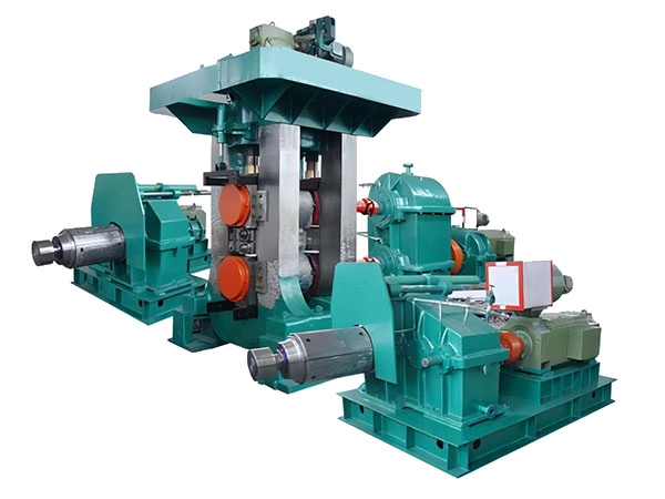
When evaluating production equipment for metal forming, choosing between a hot rolling mill and a cold rolling mill directly impacts your operational budget. While both processes reduce material thickness, their distinct thermal requirements, energy consumption, and maintenance needs create vastly different cost structures. This article dissects the financial implications of each method, helping you assess which technology aligns with your production volume, material specifications, and long-term profitability goals. We also explore how gyssljx integrates cost-saving innovations into both mill types to optimize your return on investment.
Understanding the Core Differences Between Hot and Cold Rolling
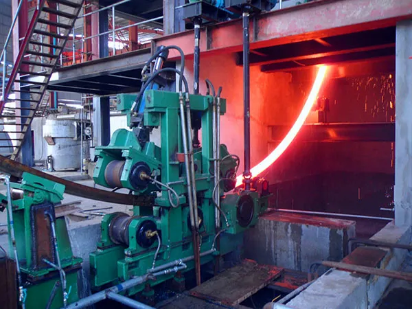
The fundamental distinction lies in processing temperature. Hot rolling occurs above the material’s recrystallization temperature, typically over 1000°C for steel, allowing significant reduction in thickness with lower mechanical force. Cold rolling is performed at or near room temperature, requiring higher power per pass but delivering superior surface finish and dimensional precision. These differences cascade into every cost factor:
- Energy consumption: Hot mills need substantial fuel or electricity for preheating furnaces, while cold mills demand more electrical power for deformation.
- Tooling wear: High-temperature contact accelerates roll degradation in hot mills; cold mills experience abrasive wear from hardened surfaces.
- Scale formation: Hot rolling generates iron oxide scale that must be removed, adding cleaning and waste-handling costs.
Direct Cost Comparison: Initial Investment and Operating Expenses
Capital Expenditure (CapEx)
Hot rolling mills generally require larger initial capital due to furnace systems, material handling for high temperatures, and massive structural frames. A complete hot mill line can cost 30–50% more than an equivalent cold mill. However, for high-tonnage production (over 500,000 tons annually), the per-unit investment may still be lower with hot rolling.
…
For more information about hot rolling mills versus cold rolling mills: which can reduce production costs, please click to visit:https://www.gyssljx.com/a/news/difference-between-hot-rolling-mill-and-cold-rolling-mill.html