The semiconductor industry is undergoing a paradigm shift as next-generation applications demand devices that are faster, more energy-efficient, and capable of operating under extreme conditions. Among these advancements, silicon carbide (SiC) semiconductors have emerged as a transformative technology, powering sectors from electric vehicles to renewable energy systems. However, producing high-quality SiC wafers requires materials that meet rigorous standards for thermal stability, chemical inertness, and structural integrity. This is where high-purity isostatic graphite has proven to be indispensable.

Role of High-Purity Isostatic Graphite in SiC Semiconductor Production

Isostatic graphite used in SiC semiconductor production

High-purity isostatic graphite is a specialized form of graphite produced through isostatic pressing, a process that applies uniform pressure in all directions to a graphite powder preform. This method ensures a remarkably consistent density, low porosity, and superior mechanical strength compared to conventional graphite forms. For SiC semiconductor manufacturers, these properties translate into unparalleled performance during the crystal growth and wafer fabrication processes.

One of the most critical applications of high-purity isostatic graphite is in SiC crystal growth using the sublimation or physical vapor transport (PVT) method. During this process, SiC powder is heated to extremely high temperatures, often exceeding 2000°C, to facilitate the formation of single crystals. Graphite components, including crucibles, heaters, and thermal shields, are exposed to intense thermal cycles and chemically reactive environments. Impurities or structural inconsistencies in conventional graphite can lead to wafer defects, inclusions, and reduced yields. High-purity isostatic graphite mitigates these risks by offering uniform thermal conductivity and exceptional resistance to chemical reactions, ensuring that the resulting SiC wafers meet stringent electronic and structural specifications.

In addition to thermal and chemical performance, dimensional stability is a significant factor in next-gen SiC semiconductor production. During prolonged high-temperature operations, standard graphite may deform, warp, or experience differential expansion, introducing stresses into the SiC crystal lattice. High-purity isostatic graphite, with its isotropic structure, minimizes anisotropic expansion and maintains precise geometries, supporting consistent crystal growth and reducing the likelihood of internal defects. This characteristic is particularly vital for the production of large-diameter wafers, which are increasingly required to meet the demands of high-power devices and industrial-scale applications.

For more detailed information on the isostatic graphite used in SiC semiconductor production, please click to visit:https://www.czgraphite.com/a/news/isostatic-graphite-used-in-sic-semiconductor-production.html

Thin section bearings have become increasingly critical in modern industrial applications due to their compact size, lightweight design, and ability to handle high-precision rotational loads. From robotics and aerospace components to medical devices and machine tools, these bearings provide engineers with exceptional flexibility where space and weight constraints are paramount. However, the very characteristics that make thin section bearings attractive—reduced cross-sectional height and precision tolerances—also make them more susceptible to installation errors, particularly ring distortion. Preventing ring distortion in thin section bearing installation is essential to ensure optimal performance, extended service life, and reduced maintenance costs.

Understanding Ring Distortion in Thin Section Bearings

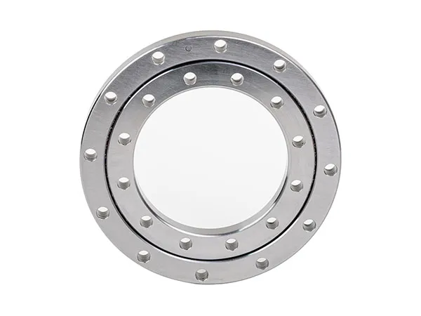
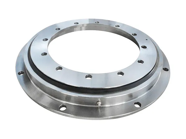
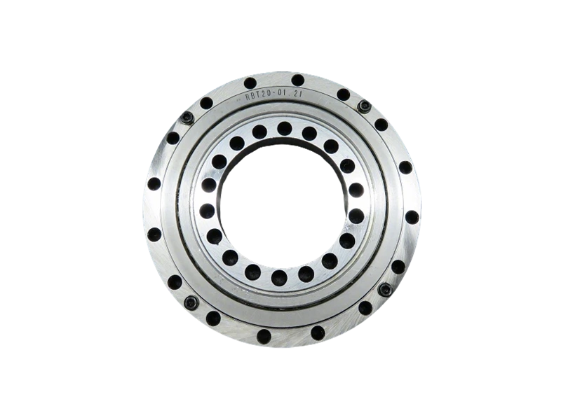
Thin Section Bearings

Ring distortion occurs when excessive or uneven forces are applied to the inner or outer rings of a bearing during installation. In thin section bearings, the ring walls are much thinner than those in standard bearings, which means even minor deviations in mounting can lead to permanent deformation. Distorted rings compromise the bearing’s ability to rotate smoothly, introduce uneven stress distribution, and may cause premature failure of rolling elements or raceways. The consequences are often amplified in high-speed or precision applications, where even microscopic deformations can translate into significant operational inefficiencies.

Common causes of ring distortion include:

Misalignment during assembly – Improper alignment between the shaft and housing can introduce bending stresses on the bearing rings.

Excessive mounting force – Using hammers or presses without appropriate controls can deform thin rings.

Incorrect tool usage – Applying pressure on the wrong surfaces or using non-specialized tools increases the risk of ring damage.

Thermal expansion errors – Rapid heating or cooling without proper guidance can induce uneven expansion, leading to distortion.

Best Practices for Preventing Ring Distortion

Preventing ring distortion begins with careful planning and the use of proper installation techniques. Engineers and technicians should follow a systematic approach to reduce the risk of damage:

1. Select the Right Tools and Equipment

Specialized mounting tools such as bearing sleeves, spanner rings, and hydraulic presses are essential for thin section bearings. These tools are designed to apply uniform force to the bearing rings without concentrating pressure on specific points, which minimizes the risk of distortion. Additionally, torque-controlled wrenches and alignment jigs help ensure that the applied forces remain within manufacturer-recommended limits.

For more detailed information on the preventing ring distortion in thin section bearing installation, please click to visit:https://www.prsbearings.com/a/news/preventing-ring-distortion-in-thin-section-bearing-installation.html

Thin section four-point contact bearings have become an indispensable component in precision machinery, aerospace applications, robotics, and other high-performance systems. Their compact size combined with high load-carrying capacity makes them ideal for applications where space is limited but performance cannot be compromised. Understanding how to calculate load capacity for thin section four-point contact bearings is critical for engineers and designers to ensure system reliability, longevity, and optimal performance.

Understanding the Basics of Thin Section Four-Point Contact Bearings

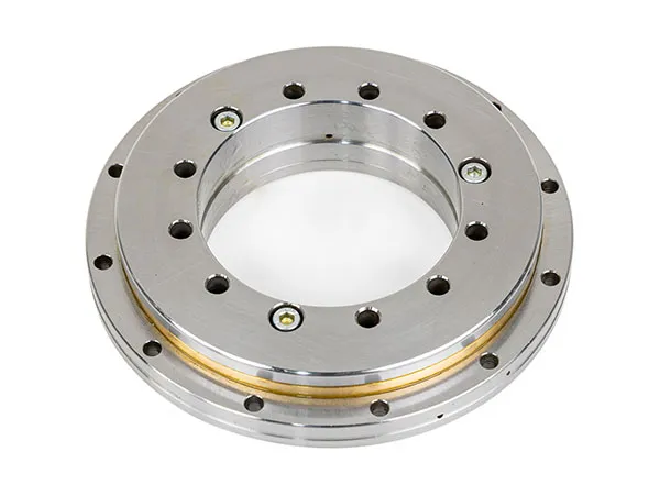
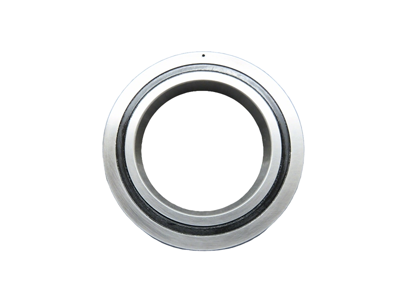
Thin Section Four-Point Contact Bearings

Thin section four-point contact bearings are unique because they are designed to accommodate axial loads in both directions, in addition to radial loads. Unlike standard ball bearings, these bearings distribute loads across four points of contact, which reduces stress concentration and improves rigidity. They are often used in robotic joints, rotary tables, and optical equipment where precise motion control is essential.

The calculation of load capacity is influenced by several factors, including the bearing’s geometry, material properties, preload, and operational environment. By carefully analyzing these factors, engineers can select the appropriate bearing size and ensure that it operates safely within its design limits.

Key Factors Affecting Load Capacity

Before diving into the calculations, it is important to identify the primary factors that affect the load capacity of thin section four-point contact bearings:

Bearing Geometry: The inner and outer ring diameters, cross-section width, and contact angle directly influence the load distribution and stress levels within the bearing. A larger cross-section and higher contact angle typically increase load capacity.

Material Strength: Bearings made from high-quality, hardened steel or advanced ceramics can sustain higher loads compared to those made from standard materials. Material fatigue limits must be considered when calculating load capacity for long-term operation.

Preload Conditions: Applying proper preload can enhance stiffness and reduce deflection. However, excessive preload may increase friction and heat generation, reducing bearing life.

Operating Environment: Temperature, lubrication, and contamination impact the effective load capacity. Bearings operating in high-temperature or contaminated environments require derating factors to account for reduced performance.

Dynamic vs. Static Loads: The bearing load capacity differs for dynamic (rotating) versus static (stationary) applications. Dynamic capacity considers fatigue life under repeated loading cycles, whereas static capacity focuses on the bearing’s ability to withstand peak loads without permanent deformation.

For more detailed information on the calculation of the load capacity of thin-section four-point contact bearings, please click to visit:https://www.prsbearings.com/a/news/calculation-of-the-load-capacity-of-thin-section-four-point-contact-bearings.html

In modern industrial applications, the demand for compact, high-precision rotational components has grown significantly. Thin section bearings have emerged as a solution, providing exceptional performance in confined spaces without compromising load capacity or rotational accuracy. Among the diverse designs available, the choice of contact style plays a pivotal role in determining the bearing’s performance under varying operating conditions. This article explores thin section bearing Type A vs Type C vs Type X contact styles, highlighting their structural differences, operational advantages, and industry applications.

What Are Thin Section Bearings?

Thin section bearings are specialized bearings characterized by their small cross-sectional height relative to their bore diameter. This design enables engineers to integrate rotational components into applications where conventional bearings would be too bulky or heavy. Despite their reduced profile, these bearings maintain high load-carrying capacity, rigidity, and operational precision, making them ideal for robotics, aerospace, medical devices, and automation equipment.

The contact style of a bearing, which refers to how the rolling elements interact with the raceway surfaces, significantly impacts its axial and radial load handling, rotational smoothness, and resistance to misalignment. Understanding the distinctions among Type A, Type C, and Type X contact styles is crucial for engineers seeking optimal performance in thin section bearing applications.

Thin Section Bearings

Type A Contact Style: Angular Contact with Standard Load Distribution

Type A thin section bearings utilize an angular contact design where the rolling elements make contact with the raceways at a moderate angle. This configuration allows the bearing to handle both radial and moderate axial loads in one direction. The Type A style is especially beneficial in applications requiring precise axial positioning while maintaining high rotational accuracy.

Advantages:

Balanced load distribution between radial and axial directions.

High rotational accuracy suitable for robotic joints and positioning systems.

Versatility in handling moderate axial forces without the need for additional support bearings.

Limitations:

Axial load capacity is directional; misalignment can reduce performance.

Not ideal for applications with high axial loads in both directions simultaneously.

Industries such as semiconductor equipment manufacturing and precision assembly machinery often favor Type A thin section bearings for their combination of compact size and balanced load handling.

For more detailed information on the thin section bearing type A vs type C vs type X contact styles, please click to visit:https://www.prsbearings.com/a/news/thin-section-bearing-type-a-vs-type-c-vs-type-x-contact-styles.html

In the realm of aggregate processing and mining operations, the choice of feeding method for impact crushers significantly influences operational efficiency, energy consumption, and overall production output. Two prevalent feeding strategies are gravity-fed and conveyor-fed systems, each offering distinct advantages and limitations. Understanding the nuances of gravity-fed vs conveyor-fed impactor efficiency is crucial for plant engineers, production managers, and equipment purchasers who aim to maximize throughput while minimizing operational costs.

Understanding Gravity-Fed Impactors

https://www.yd-crusher.com/impact-crusher.html

Gravity-fed impactors operate by utilizing the natural force of gravity to move material from the feed hopper directly into the crushing chamber. This feeding method is often preferred for smaller-scale operations or for applications where material flow is consistent and predictable. The simplicity of the gravity-fed design reduces mechanical complexity and maintenance requirements, as fewer moving components are involved in the feeding process.

From an efficiency standpoint, gravity-fed impactors can provide excellent crushing performance when material characteristics are uniform. The consistent gravitational feed allows for optimal distribution of material onto the rotor, reducing the likelihood of clogging and uneven wear. However, these systems are less adaptable to variable material volumes or high-capacity operations. During peak production, a gravity-fed system may experience fluctuations in material supply, which can reduce crusher efficiency and result in uneven product size distribution.

Conveyor-Fed Impactors: Enhancing Throughput and Control

Conveyor-fed impactors, by contrast, use belt conveyors or vibratory feeders to deliver material into the crusher at a controlled and consistent rate. This feeding strategy is widely adopted in large-scale operations where throughput optimization and process stability are paramount. By precisely controlling the feed rate, conveyor-fed systems minimize energy losses caused by overloading or underfeeding, which directly improves operational efficiency.

Additionally, conveyor-fed impactors can handle a broader range of material sizes and types, including those with varying moisture content or abrasiveness. The ability to regulate feed rate allows operators to maintain consistent crushing conditions, which contributes to uniform product quality and extends the service life of wear parts such as blow bars and impact plates. For facilities aiming to integrate automation or advanced process monitoring, conveyor-fed systems provide the flexibility necessary for real-time operational adjustments, further enhancing efficiency.

For more detailed information on the gravity-fed vs conveyor-fed impactor efficiency, please click to visit:https://www.yd-crusher.com/a/news/gravity-fed-vs-conveyor-fed-impactor-efficiency.html

In the evolving landscape of mining and aggregate processing, understanding the financial implications of equipment operation has become critical for operational efficiency. Among the various crushing solutions available, impact crushers have gained significant attention due to their high reduction ratios, ability to handle medium-hard to soft materials, and flexibility in producing a consistent particle size. However, as mining projects expand and production scales increase, operators are increasingly concerned with the impact crusher operating cost per ton 2026, a key metric that directly affects project profitability.

What Determines Impact Crusher Operating Costs?

Impact crusher

Calculating the operating cost per ton for an impact crusher involves a multifaceted approach. Costs are influenced by several factors, including:

Energy Consumption: Impact crushers generally consume more energy than jaw crushers for similar feed sizes due to their high-speed rotor mechanism. However, technological improvements in rotor design and motor efficiency are gradually reducing energy consumption in newer models.

Wear Parts and Maintenance: The cost of wear components such as blow bars, impact plates, and rotors significantly impacts the operating cost per ton. In 2026, manufacturers are focusing on high-chrome and alloy steel materials that extend component life, thereby reducing frequent replacements and downtime.

Labor and Operational Efficiency: Skilled operators can optimize feed rates, rotor speed, and reduction ratios to minimize unnecessary wear and maximize throughput. Automation technologies, including remote monitoring and predictive maintenance, are becoming more prevalent, helping reduce human error and labor costs.

Material Characteristics: The type and hardness of the material being processed directly influence operating costs. Softer materials like limestone require less wear-intensive processing, whereas harder rocks such as basalt or granite can accelerate wear and energy consumption.

Throughput and Load Management: Efficient load distribution and proper crusher sizing can reduce overloading, which not only saves energy but also extends equipment lifespan. Oversized or undersized crushers can lead to inefficiencies that increase the cost per ton.

For more detailed information on the impact crusher operating cost per ton 2026, please click to visit:https://www.yd-crusher.com/a/news/impact-crusher-operating-cost-per-ton-2026.html

Impact crushers are widely used in mining, construction, and recycling industries for their ability to efficiently reduce large rocks and materials into manageable sizes. While these machines are designed to handle high workloads, one common operational challenge is excessive vibration. Excessive vibration not only affects the crusher’s performance but also increases maintenance costs, reduces equipment lifespan, and poses safety risks for operators. Understanding the causes and implementing effective troubleshooting measures is crucial for maintaining smooth operations and extending the life of your impact crusher.

Understanding the Causes of Excessive Vibration

Excessive vibration in impact crushers can arise from a variety of mechanical, operational, and environmental factors. Identifying the root cause is the first step toward an effective solution. Common causes include:

Imbalanced Rotor or Blow Bars

The rotor in an impact crusher rotates at high speeds, and even a minor imbalance can generate strong vibrations. Uneven wear or damage to blow bars can further amplify the imbalance, causing the crusher to vibrate excessively.

Loose or Worn Bearings

Bearings are critical components that support the rotor and other moving parts. Loose, worn, or improperly lubricated bearings increase friction and create abnormal vibrations during operation.

Incorrect Material Feed

Feeding oversized or unevenly distributed material can cause uneven load distribution inside the crushing chamber. This imbalance produces vibration and may even damage internal components.

Foundation and Mounting Issues

A poorly designed or unstable foundation can transmit vibration throughout the crusher and surrounding equipment. Bolts and mounting fixtures that are not properly tightened may also contribute to vibration problems.

Mechanical Wear and Fatigue

Over time, structural components such as shafts, frames, and housings may develop cracks or fatigue. Even small defects can magnify vibrations during high-speed operation.

For more detailed information on the troubleshooting excessive vibration in impact crushers, Impact crusher maintenance, please click to visit:https://www.yd-crusher.com/a/news/troubleshooting-excessive-vibration-in-impact-crushers.html

When selecting materials for architectural panels, roofing, signage, or industrial equipment, the choice of surface finish on aluminum coils plays a critical role in determining longevity, maintenance needs, and overall performance. A common debate in the industry revolves around anodized aluminum coil vs painted: which is more durable? Understanding the differences between these two finishes can help manufacturers, designers, and end-users make informed decisions for projects that require both aesthetic appeal and structural integrity.

Understanding Anodized Aluminum Coils

Anodizing is an electrochemical process that converts the surface of aluminum into a durable, corrosion-resistant oxide layer. Unlike paint, which merely sits on top of the metal, anodized aluminum becomes part of the material itself. This oxide layer ranges in thickness depending on the application, with architectural applications typically using layers between 5 to 25 microns. The benefits of anodized aluminum include enhanced resistance to UV radiation, excellent wear resistance, and superior protection against corrosion in both indoor and outdoor environments.

One of the most notable characteristics of anodized aluminum is that the finish is colorfast. Unlike painted surfaces that can fade or peel over time, the anodized layer retains its appearance for decades with minimal maintenance. Moreover, anodized aluminum is highly resistant to scratching, which makes it an ideal choice for high-traffic applications, such as exterior cladding or elevator panels, where durability and long-term appearance are crucial.

The Advantages and Limitations of Painted Aluminum

Painted aluminum coils, in contrast, rely on a coating system to protect the metal surface. Modern coatings, such as PVDF (polyvinylidene fluoride) and polyester paints, offer a wide range of colors, textures, and gloss levels. High-quality painted aluminum can resist weathering, UV degradation, and chemical exposure to a certain degree, making it suitable for decorative facades, signage, and automotive components.

However, the durability of painted aluminum depends heavily on the quality of the coating and the preparation of the aluminum substrate. Poor surface preparation, low-quality paint, or exposure to harsh environments can lead to issues such as chipping, cracking, and fading over time. Unlike anodized surfaces, painted aluminum requires regular maintenance to preserve its aesthetic appeal and protective properties. In extreme conditions, such as coastal or industrial areas, painted aluminum may deteriorate faster than anodized options due to chemical corrosion or abrasion.

For more detailed information on the anodized aluminum coil vs painted, please click to visit:https://www.dw-al.com/a/news/anodized-aluminum-coil-vs-painted.html

As businesses expand and the demand for durable, cost-effective infrastructure grows, commercial steel buildings have become a preferred choice for many industries. However, understanding the commercial steel building cost per square foot 2026 is essential for accurate budgeting and project planning. Unlike traditional construction materials such as concrete or wood, steel offers unique advantages, including longevity, resistance to environmental stress, and design flexibility, but its pricing can vary widely depending on multiple factors.

Factors Influencing the Cost Per Square Foot

The cost of a commercial steel building is not fixed and is influenced by a combination of material, labor, design, and regional economic conditions. In 2026, these factors are more relevant than ever due to fluctuating raw material prices and evolving construction standards.

Material Quality and Grade of Steel

Steel comes in various grades, each with different structural strength and durability. High-strength steel with enhanced corrosion resistance can increase the cost per square foot but provides a longer lifespan, which reduces long-term maintenance expenses. Choosing the right steel grade involves balancing initial investment with projected operational efficiency.

Building Size and Layout Complexity

Larger commercial buildings typically benefit from economies of scale, potentially lowering the cost per square foot. However, complex layouts with multiple levels, large open spaces, or special structural requirements can increase fabrication and installation costs. Architects and engineers must consider load-bearing requirements and roof design when estimating expenses.

Insulation, Roofing, and Exterior Finish

While the steel frame provides the core structure, finishing materials such as insulated panels, roofing systems, and exterior cladding significantly affect total costs. In 2026, energy-efficient insulation and advanced roofing solutions are increasingly in demand, which can slightly raise the per-square-foot cost but yield savings in heating, cooling, and maintenance over time.

Labor Costs and Regional Differences

Labor costs vary across regions due to differences in wages, availability of skilled workers, and local construction regulations. Urban areas with higher labor rates may see increased construction costs, while regions with established steel building industries might offer more competitive pricing. Understanding regional labor trends is critical for precise budgeting.

Permitting, Compliance, and Additional Services

Obtaining permits and ensuring compliance with local building codes adds to overall costs. In addition, services such as foundation work, utility installation, and project management contribute to the total cost per square foot. Businesses should include these factors in their financial projections to avoid unexpected expenditures.

For more detailed information on the commercial steel building cost per square foot 2026, please click to visit:https://www.hcggsteel.com/a/news/commercial-steel-building-cost-per-square-foot-2026.html

Graphite electrodes play a critical role in electric arc furnaces (EAF) and ladle furnaces, where they are subjected to extreme temperatures often exceeding 3000°C. These electrodes are preferred for their high conductivity, thermal stability, and mechanical strength. However, despite their inherent advantages, graphite electrodes are highly susceptible to oxidation when exposed to high temperatures in the presence of oxygen. Oxidation not only reduces the electrode’s lifespan but also increases operational costs and compromises furnace efficiency. Understanding how to prevent oxidation in graphite electrodes at high temperatures is therefore essential for industries relying on electric arc processes.

Understanding the Oxidation Mechanism in Graphite Electrodes

Graphite oxidation occurs when carbon atoms in the electrode react with oxygen to form carbon monoxide (CO) or carbon dioxide (CO₂). This chemical reaction accelerates at high temperatures and is further exacerbated by the presence of moisture or impurities in the furnace environment. The reaction can be summarized as follows:

C + O₂ → CO₂

2C + O₂ → 2CO

As oxidation progresses, the electrode loses structural integrity, resulting in increased electrical resistance, reduced thermal conductivity, and surface erosion. Ultimately, this leads to frequent electrode replacements and increased downtime, which can significantly impact production efficiency and operational costs.

Effective Strategies to Prevent Oxidation

Preventing oxidation in graphite electrodes requires a combination of material improvements, operational practices, and protective measures. Below are the most effective strategies that can be implemented:

1.Use High-Density, Impurity-Free Graphite Electrodes

The quality of graphite electrodes is the first line of defense against oxidation. Electrodes with high density and low porosity reduce oxygen penetration into the carbon matrix. Additionally, selecting electrodes with minimal impurities, such as metallic residues, reduces the catalytic sites for oxidation reactions. Manufacturers should prioritize electrodes produced from premium petroleum coke and needle coke with uniform particle sizes, as these materials exhibit superior thermal stability.

2.Apply Protective Coatings

Graphite electrodes can be coated with anti-oxidation agents such as pitch or silicon carbide layers. These coatings form a barrier on the electrode surface, reducing direct exposure to oxygen. Regularly inspecting and reapplying these coatings ensures consistent protection. In some advanced applications, ceramic-based coatings have been shown to offer longer-lasting resistance to high-temperature oxidation.

3.Optimize Furnace Atmosphere

Controlling the furnace atmosphere is crucial in minimizing graphite oxidation. Reducing the oxygen concentration in the furnace through inert gas purging or maintaining a slightly reducing environment can slow down the oxidation rate. Operators should also ensure that moisture content is minimized, as water vapor can accelerate carbon oxidation at elevated temperatures.

4.Implement Controlled Electrode Handling

Improper handling of graphite electrodes can create surface cracks, exposing fresh carbon to oxygen and accelerating oxidation. Training personnel to handle electrodes carefully during storage, transport, and installation can significantly reduce mechanical damage. Additionally, storing electrodes in dry, temperature-controlled conditions prevents premature oxidation before use.

5.Monitor Electrode Temperature and Current Load

Graphite electrodes are most vulnerable to oxidation at the tip, where temperatures and electrical loads are highest. Ensuring the furnace operates within recommended voltage and current limits helps maintain uniform electrode temperature and reduces localized overheating. Advanced monitoring systems can track electrode wear and temperature distribution, allowing timely adjustments to prevent excessive oxidation.

6.Regular Maintenance and Inspection

Frequent inspection of graphite electrodes can detect early signs of oxidation, such as surface pitting or darkening. Removing oxidized sections and applying protective coatings can extend electrode life. Additionally, maintaining furnace integrity, including seals and insulation, ensures that oxygen intrusion is minimized.

For more detailed information on the how to prevent oxidation in graphite electrodes at high temperatures, please click to visit:https://www.czgraphite.com/a/news/how-to-prevent-oxidation-in-graphite-electrodes-at-high-temperatures.html