For any operation that generates scrap metal—whether from machining, stamping, or demolition—transportation costs often eat into already thin margins. Loose scrap is bulky, inefficient to load, and expensive to haul. The solution is straightforward: compact your scrap into dense briquettes. By reducing volume by up to 90%, briquetting transforms your waste stream into a high-value, easily transportable commodity. This article examines the economics, the technology, and the practical steps to lower your transport costs using briquetting equipment from ZYmining, a trusted name in industrial compaction solutions.
The True Cost of Loose Scrap Transport
Before exploring the benefits of briquetting, it is essential to understand how loose scrap drives up logistics expenses. Transport companies charge by weight or by volume—whichever yields higher revenue. For loose scrap, volume is almost always the limiting factor. A truck loaded with crumpled turnings or shredded sheet metal may reach its volumetric capacity while still being well under its legal weight limit. This means you pay for a full truck but move far less mass than possible.
- Low payload per trip: Loose scrap can fill a 40-yard container with only 8–10 tons, whereas briquetted scrap of the same density can achieve 20–25 tons per container.
- Higher frequency of hauls: More trips are required to move the same tonnage, increasing fuel, labor, and administrative costs.
- Risk of spills and contamination: Loose scrap can shift during transit, causing safety hazards and potential environmental fines.
- Reduced resale value: Scrap yards often penalize low-density material because it requires recompaction before processing.
How Compacting Scrap into Briquettes Reduces Costs
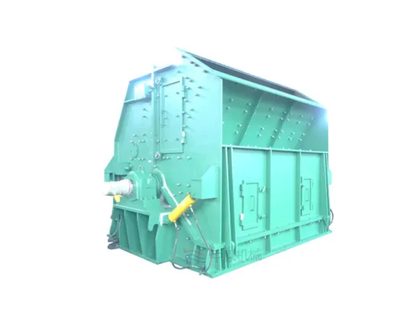
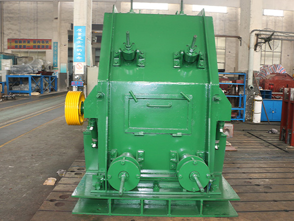
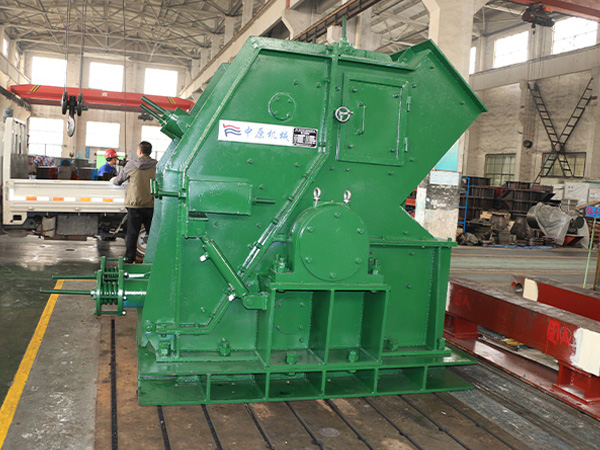
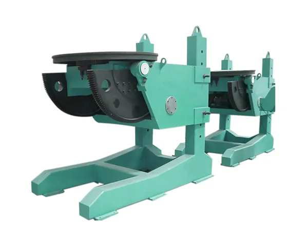
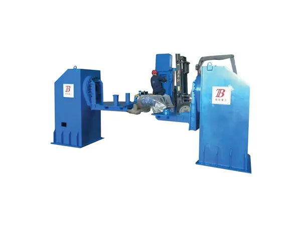
Briquetting applies high pressure to compress loose metal chips, swarf, or other ferrous/non-ferrous scrap into solid cylinders or pucks. The process removes air gaps and interlocks the particles, creating a dense, cohesive product.
…
For more information on compressing waste into coal briquettes to reduce transportation costs, please click here:https://www.zymining.com/en/a/news/scrap-briquetting-sa.html